Communication system power loss notification via detection of reverse bias state of a diode based on a threshold voltage

a technology of reverse bias state and communication system, applied in the field of system and method of power loss notification, can solve the problems of increasing the time between power supply and power loss, affecting the transmission of power loss signals, so as to reduce or eliminate some or all of the problems and disadvantages

Inactive Publication Date: 2005-05-17
SAGEMCOM BROADBAND
View PDF10 Cites 2 Cited by
  • Summary
  • Abstract
  • Description
  • Claims
  • Application Information

AI Technical Summary

Benefits of technology

[0006]The present invention recognizes a need for an improved system and method for power loss notification, which reduce or eliminate some or all of the problems and disadvantages associated with prior systems and methods.
[0010]Numerous technical advantages can be gained through various embodiments of the invention. Various embodiments of the invention may exhibit none, some, or all of the following advantages. For example, in one embodiment of the invention, a modem is provided that quickly identifies when a power loss occurs. The modem may then generate a power loss signal informing a central office or other network element of the power loss. By quickly identifying when the power loss occurs, a shorter period of time may elapse between the time the modem loses power and the time the modem detects the power loss. This helps to reduce or eliminate the likelihood that the modem will be unable to generate and transmit the power loss signal to the central office or other network element.
[0011]Some embodiments of the invention also simplify the circuitry used in the modem. For example, in one embodiment, fewer capacitors may be coupled to the power supply and used in the modem. This helps to reduce the size and cost of the modem. Also, the modem is not limited to the use of a “level detector.” The modem may, for example, use any digital detector operable to detect the presence or absence of a voltage signal. Although a level detector may still be used to detect a power loss, other less expensive circuits can also be used.

Problems solved by technology

A problem with this approach is that a relatively long period of time may elapse between the time the modem loses power and the time the power loss circuitry detects the power loss.
This increases the time between the power loss and the detection of the power loss, and this period of time is often important.
If too much time elapses before the circuitry detects the power loss, the modem will not have enough power to generate and transmit the power loss signal.
Another problem with this approach is that it typically increases the amount of circuitry used in the modem.
These additional components increase the overall cost of the modem and take up space that could be used for other elements in the modem.

Method used


Image

  • Communication system power loss notification via detection of reverse bias state of a diode based on a threshold voltage
  • Communication system power loss notification via detection of reverse bias state of a diode based on a threshold voltage
  • Communication system power loss notification via detection of reverse bias state of a diode based on a threshold voltage

Examples


Embodiment Construction

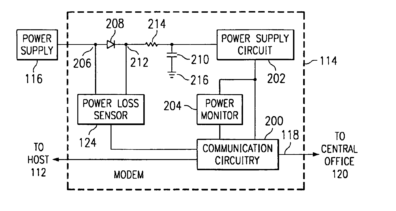
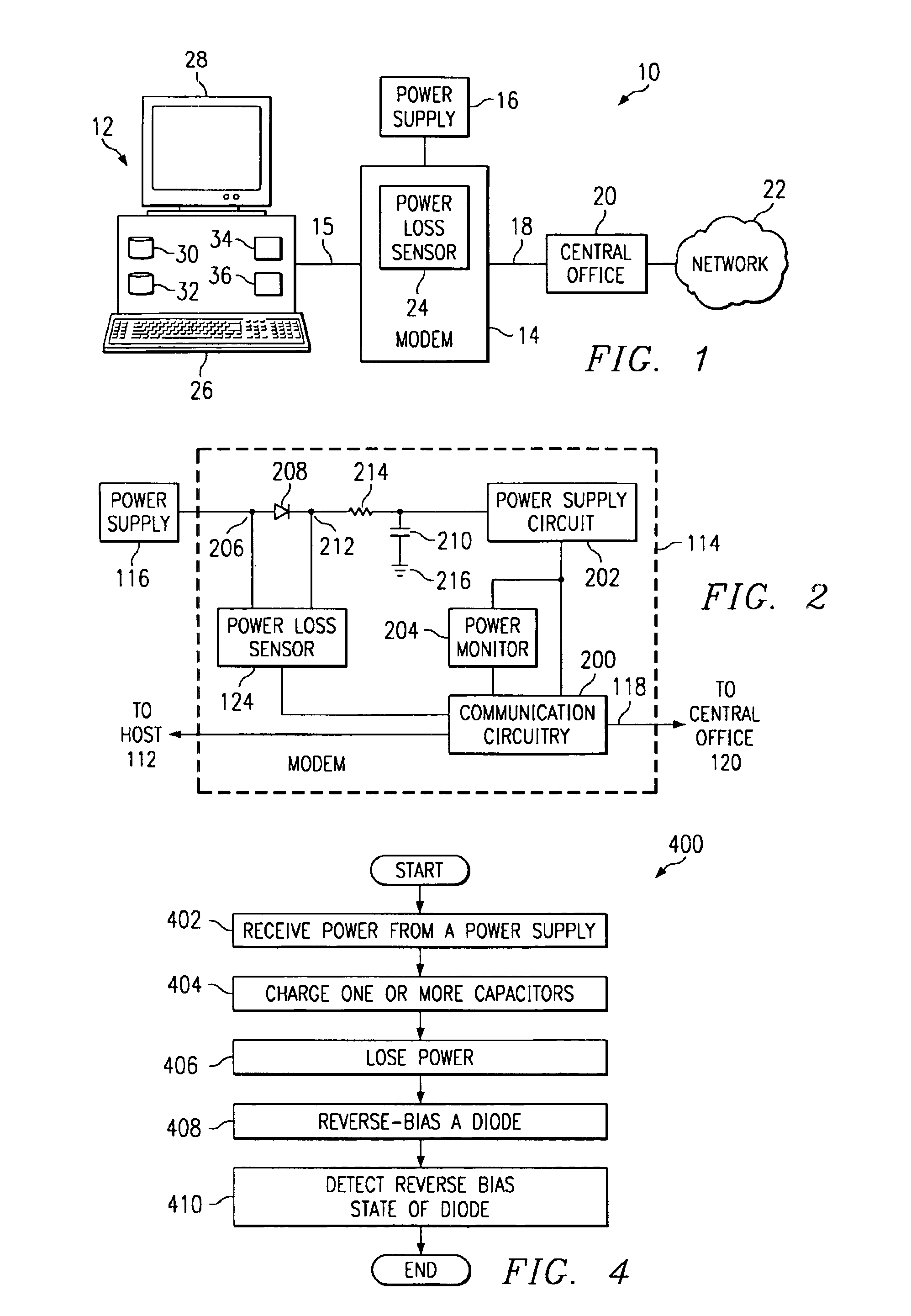
[0018]FIG. 1 is a block diagram illustrating an exemplary communication system 10 constructed according to the teachings of the present invention. In the illustrated embodiment, system 10 includes one or more host computers 12 and a modem 14 coupled to a power supply 16. A communication link 18 facilitates communication between the modem 14 and other network elements, such as a central office 20 coupled to a network 22. Other embodiments of system 10 may be used without departing from the scope of the present invention.

[0019]In general, modem 14 facilitates communication between host 12 and network 22. Modem 14 may, for example, communicate information to and receive information from network 22 through central office 20. Modem 14 also receives power from power supply 16, and modem 14 includes a power loss sensor 24. Power loss sensor 24 detects when modem 14 loses power, or stops receiving at least a threshold voltage, from power supply 16. When power loss sensor 24 detects a power ...


PUM


Abstract

In one aspect of the invention, a method for power loss notification includes receiving at least a threshold voltage from a power supply. The method also includes charging at least one capacitor when the power supply is supplying at least the threshold voltage. The method further includes failing to receive at least the threshold voltage from the power supply, and reverse biasing at least one diode coupled between the power supply and the at least one capacitor. In addition, the method includes detecting the reverse bias state of the diode.

Description

TECHNICAL FIELD OF THE INVENTION[0001]This invention relates generally to power delivery systems, and more particularly to a system and method for power loss notification.BACKGROUND OF THE INVENTION[0002]Computers often communicate over a network using a modem at a subscriber's location. This modem facilitates the communication of data from the subscriber to a remote location, such as to a central office of a service provider. The modem typically receives power from an external power supply. When the modem loses power, the modem generally informs the central office or other remote location of the power loss. This allows the central office to stop transmitting data to the modem when the modem is unable to receive that data.[0003]Modems often use one or more capacitors to store a voltage charge from the power supply. To determine when a power loss occurs, modems typically use power loss circuitry coupled to the capacitors. The power loss circuitry operates to monitor the voltage betwe...

Claims


Application Information

Patent Timeline
Patent Type & Authority Patents(United States)
IPC IPC(8): G06F1/28
CPCG06F1/28
Inventor DOSSEY, JOHN W.DO, SANH T.
Owner SAGEMCOM BROADBAND
Why Eureka
Try Eureka