System and method for performing a single step cryoablation

Active Publication Date: 2005-05-17
CRYOCOR
View PDF24 Cites 61 Cited by
  • Summary
  • Abstract
  • Description
  • Claims
  • Application Information

AI Technical Summary

Benefits of technology

[0011]The system of the present invention further includes a balloon and a balloon catheter for interposing the balloon between the cryo-element and the target tissue. For the present invention, the balloon catheter is elongated and defines a longitudinal axis in the direction of elongation. In more detail, the balloon catheter is formed with a lumen that extends between the proximal and distal ends of the balloon catheter. The balloon is attached to the distal end of the balloon catheter and is placed in fluid communication with the lumen of the balloon catheter. With this combination of structure, a saline solution can be introduced into the balloon by pumping saline solution into the proximal end of balloon catheter at an extracorporeal location. Structurally, when inflated with a saline solution, the balloon has a substantially U-shaped cross-section in a plane substantially orthogonal to the longitudinal axis of the balloon catheter. This shape allows the balloon to surround and grip the cryo-element, and to conductively transfer heat from the target tissue through the inflated balloon to the cryo-element along substantially radial paths.
[0013]With the balloon interposed between the cryo-element and the target tissue, saline solution is pumped into the balloon causing the balloon to expand. Filling of the balloon with saline solution is continued until the expanded balloon contacts both the cryo-element and the surrounding target tissue. The shape of the balloon (i.e. the U-shape) allows the balloon to surround the cryo-element and provide a large contact area between the balloon and the cryo-element. The large contact area, in turn, provides for good heat transfer between the saline solution and the cryo-element. In addition, the expanded balloon functions to anchor the cryo-element in place at the site of the target tissue.
[0015]The system can also include a mechanism for directing energy into the “ice ball” to quickly thaw the frozen “ice ball” and restore blood flow through the affected conduit (e.g. pulmonary vein). Once the “ice ball” is thawed, the saline solution can be removed from the balloon and the balloon withdrawn from the patient's body. In one embodiment of the present invention, the system includes a radiofrequency (rf) antenna positioned near the balloon to thaw the “ice ball” and facilitate removal of the balloon from the patient.

Problems solved by technology

This often results in a non-uniform circumferential ablation that fails to form an adequate conduction block.
These structures increase the size of the distal end of the catheter, making the catheter harder to steer and navigate through the vasculature of the patient to the treatment site.
Is short, procedures requiring multiple contacts tend to be complicated, time consuming, difficult to perform, and generally unreliable.
During ablation, movements of the patient such as heartbeats and breathing can cause the ablation element to move or bounce.
Failure to prevent these movements of the ablation element relative to the target tissue can disrupt the flow of energy between the ablation element and the tissue resulting in a non-uniform ablation.
As indicated above, non-uniform ablations often result in an ineffective conduction block.

Method used


Image

  • System and method for performing a single step cryoablation
  • System and method for performing a single step cryoablation
  • System and method for performing a single step cryoablation

Examples


Embodiment Construction

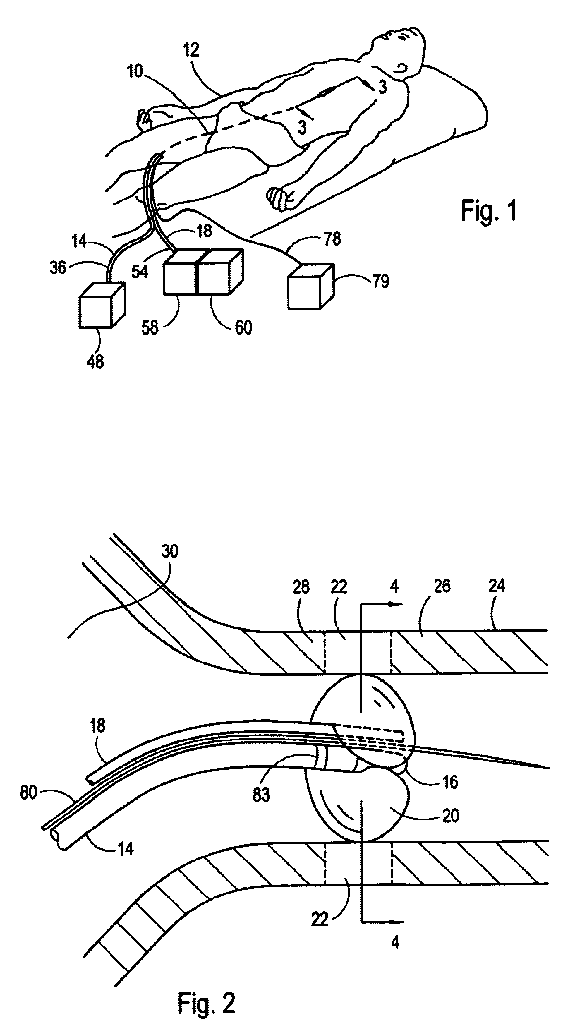
[0023]Referring initially to FIG. 1, a system 10 for cryoablating internal target tissue of a patient 12 is shown. As shown, the system 10 includes the cryo-catheter 14 for positioning a cryo-element 16 (see FIG. 2) and a balloon catheter 18 for positioning a balloon 20 at an internal treatment site of the patient 12. As further shown in FIG. 1, both the cryo-catheter 14 and balloon catheter 18 can be inserted into a peripheral artery of the patient 12 such as the femoral artery and advanced through the vasculature to a position in the upper body of the patient 12.

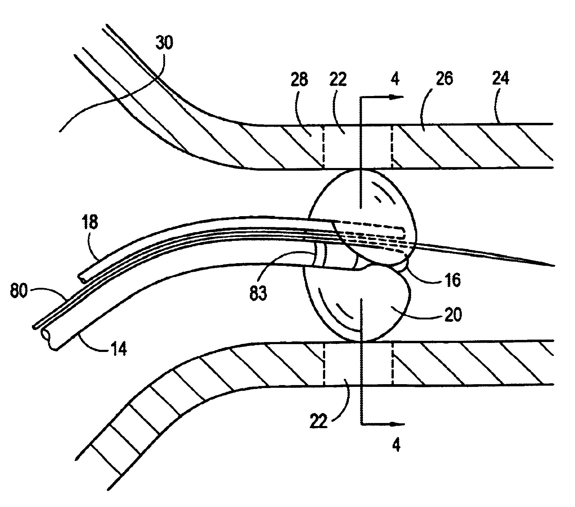
[0024]Referring now to FIG. 2, an application of the system 10 is shown wherein a substantially circumferential target tissue 22 surrounding the ostium of a pulmonary vein 24 is ablated. The resulting lesion, which can extend through the wall of the pulmonary vein 24 as shown, can function as a conduction block to prevent the transmission of electrical signals. In greater detail, the lesion can prevent electrical signals t...


PUM


Abstract

A system for cryoablating target tissue at a treatment site includes a cryo-element mounted at the distal end of a cryo-catheter. A balloon catheter is provided having a U-shaped balloon attached thereon. The cryo-element is threaded onto a pre-positioned guidewire and advanced within the patient's vasculature until the cryo-element is positioned at the treatment site. Next, the balloon is threaded onto the guidewire and advanced within the patient's vasculature using the balloon catheter. At the treatment site, the U-shaped balloon is interposed between the cryo-element and the target tissue. Saline solution is pumped into the balloon causing the U-shaped balloon to expand and contact both the cryo-element and the surrounding target tissue. Next, a refrigerant is expanded to cool the cryo-element, which in turn, freezes the saline solution. The resulting “ice ball” extracts heat from surrounding tissue resulting in the cryoablation of a substantially circumferential portion of tissue.

Description

FIELD OF THE INVENTION[0001]The present invention pertains generally to systems and methods for cryoablating internal tissue. More particularly, the present invention pertains to systems and methods for cryoablating conduction blocks to treat patients experiencing heart arrhythmias such as atrial fibrillation. The present invention is particularly, but not exclusively, useful for creating substantially circumferential ablations surrounding the ostium of a pulmonary vein in a single step.BACKGROUND OF THE INVENTION[0002]Atrial fibrillation is an irregular heart rhythm that adversely affects approximately 2.5 million people in the United States. Anatomically, two pairs of pulmonary veins are connected to the left atrium of the heart with each pair delivering blood to the heart from one of the patient's lungs. It is believed that at least one-third of all atrial fibrillation originate near the ostium of the pulmonary veins.[0003]It is further believed that the optimal technique to trea...

Claims


Application Information

Patent Timeline
IPC IPC(8): A61B18/02A61B18/00A61B17/22A61M25/00
CPCA61B18/02A61B2017/22038A61B2018/0262A61B2018/0022A61B2018/0212A61B2017/22051
Inventor LENTZ, DAVID J.
Owner CRYOCOR
Why Eureka
Try Eureka