
Insulated panel for commercial or residential construction and method for its manufacture

a technology for insulating panels and commercial or residential construction, applied in the direction of heat-insulating roofs, building repairs, etc., can solve the problems of limited tensile strength of panels, inability to support a great deal of weight on small connectors by themselves, and inability to meet the needs of construction, etc., to achieve the effect of improving the gripping surfa

Inactive Publication Date: 2005-05-17
PLYMOUTH FOAM LLC
View PDF29 Cites 75 Cited by
  • Summary
  • Abstract
  • Description
  • Claims
  • Application Information

AI Technical Summary

Benefits of technology

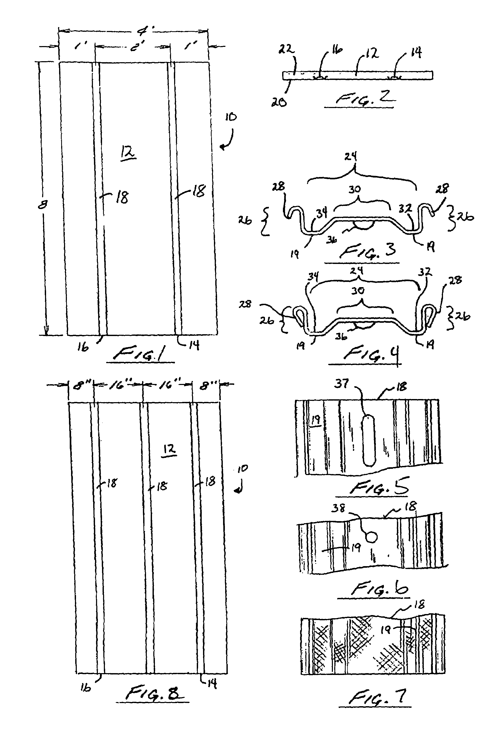
[0010]In accordance with the first embodiment of the invention, an insulated wall panel is provided including a rigid foam sheet with first and second planar sides and having first and second grooves extending substantially the full length of the sheet in a substantially parallel orientation in the first side of the sheet, a first reinforcing strip having a length, a top and a bottom, with the bottom being disposed in the first groove and the top facing outwardly away from the first groove, wherein the first strip extends substantially the full length of the sheet, a second reinforcing strip having a length, a top and a bottom with the bottom being disposed in the second groove and the top facing outwardly away from the second groove, wherein the second strip extends substantially the full length of the sheet, a first thin reinforcing layer bonded to the first planar side of the rigid foam sheet, and extending across the top of the first and second grooves, and a second thin reinforcing layer bonded to the second planar side of the sheet and extending across substantially an entire surface of the second planar side. The bottoms of the first and second strips may have two downwardly extending flanges that are oriented substantially perpendicular to the first planar side. The top of the first and second reinforcing strips may be mechanically textured over the length of the first and second strips to provide an improved gripping surface for drills and self-tapping or fine-threaded wallboard screws. The top of the first and second reinforcing strips may have a plurality of holes spaced apart at predetermined intervals along the length of the first and second reinforcing strips. The top of the first and second reinforcing strips may have a plurality of slots spaced apart at predetermined intervals along the length of the first and second reinforcing strips. The first reinforcing layer may be bonded to the rigid foam sheet to enclose the first and second reinforcing strips and to define a first vapor barrier across substantially the entire first side of the sheet. The second reinforcing layer may be bonded to the rigid foam sheet to define a second vapor barrier across substantially the entire second side of the rigid foam sheet. The first and second reinforcing layers may have a tensile strength at least 100 times as great as the tensile strength of the rigid foam sheet. A first portion of the first reinforcing layer may extend across the top of the first reinforcing strip and be placed in tension when the panel is bent away from the first reinforcing strip before the foam sheet will fracture at the first groove. A second portion of the first reinforcing layer may extend across the top of the second reinforcing strip and may be placed in tension when the panel is bent away from the second reinforcing strip before the rigid foam sheet will fracture at the second groove.
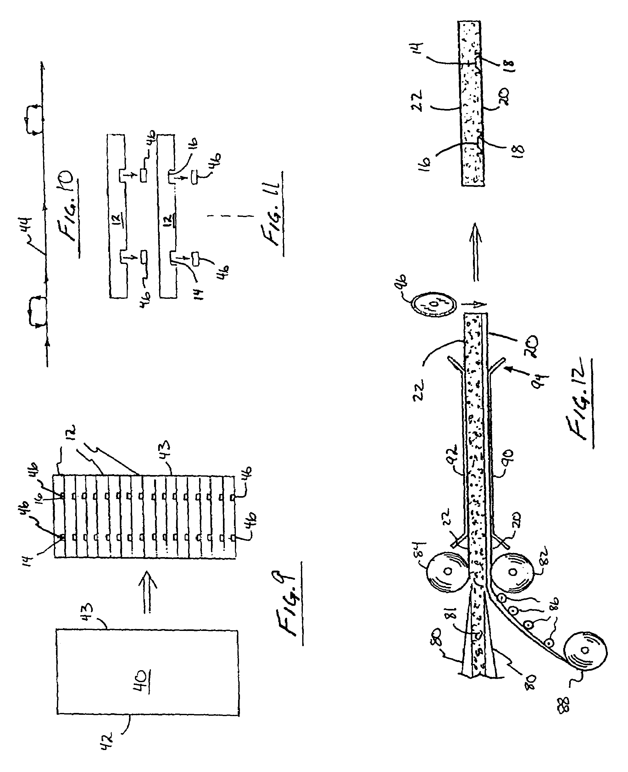
[0011]In accordance with a second embodiment of the invention, a method of manufacturing an insulated wall panel is provided that includes the steps of creating a foam block having first and second opposing sides, cutting the foam block to form a plurality of stacked individual foam sheets having first and second sides and a plurality of parallel recesses in the first side, inserting a reinforcing strip having a top and a bottom into each of the plurality

Problems solved by technology

One continuing problem with the use of rigid foam panels has been their fragility as compared to other building materials, such as wood, steel, fiberglass and the like.
The panels have limited tensile strength, and therefore cannot be used by themselves to support a great deal of weight on small connectors, such as nails and screws.
Furthermore, the forces needed to attach nails and screws to a wall or ceiling of a house or commercial building when doing original construction or repair can quite easily damage the foam panels during installation.
When foam panels are used to form an insulated sheath around a wall that is being constructed, remodeled, or repaired, some of the most difficult issues are how to attach the foam panels.
Since they are easily crushed, they cannot be used as an outer surface covering by themselves, or with a coat of paint, for example.
One cannot easily, and in many cases may not wish to attach the layer of wall covering directly to the wall or studs behind the rigid foam paneling.
For example, when attaching interior wall covering to a concrete wall, particularly an exterior concrete wall, it is especially bad to have fasteners such as nails or screws penetrating the wall-covering passing through the rigid foam layer, and being embedded in the concrete wall.
Another disadvantage to plain rigid foam sheets is their tendency to obscure the location of appropriate hanging points for the wall coverings that are subsequently attached through them to a wall.
When the subsequent layer of wall covering, such as siding or wallboard is attached, it is difficult, if not impossible to identify the location of the studs or trusses to which the foam was attached, and to which the wall covering must be attached as well.
These devices are notoriously unreliable, sensing as they do, the presence of a stud by capacitive or inductive means.

Method used


Image

  • Insulated panel for commercial or residential construction and method for its manufacture
  • Insulated panel for commercial or residential construction and method for its manufacture
  • Insulated panel for commercial or residential construction and method for its manufacture

Examples


Embodiment Construction

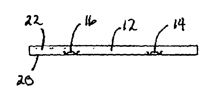
[0027]Referring now to FIGS. 1 and 2, an insulated foam panel 10 is shown that includes an rigid foam sheet 12 having two grooves 14, 16 into which two reinforcing strips 18 are disposed. The panel is preferably four feet wide by eight feet long (4′×8′) and between one and three inches (1″–3″) in thickness. The two reinforcing strips are preferably equidistantly spaced from the center of the panel two feet (2′) apart leaving a one-foot (1′) margin on either side. In this manner, when the panels are placed adjacent to each other by abutting their edges in a checkerboard arrangement, a continuous expanse of equidistantly spaced reinforcing strips on two foot centers will be provided.

[0028]On the outer surfaces of panel 10 are two thin reinforcing sheets 20 and 22. The first of these, sheet 20, extends completely across the side of the rigid foam sheet proximate to the reinforcing strips. The second of these, sheet 22, extends completely across and covers the entire surface of the oppo...


PUM

PropertyMeasurementUnit
Lengthaaaaaaaaaa
Lengthaaaaaaaaaa
Lengthaaaaaaaaaa

Abstract

A method and apparatus for making an rigid foam insulating panel is disclosed. The panel includes an rigid foam sheet with a plurality of grooves or recesses in which reinforcing strips are placed. Both sides of the sub-assembly are covered with a reinforcing sheet made of plastic, paper, foil, or a combination thereof. These reinforcing sheets are bonded to the surface of the rigid foam sheet and provide structural support to the sheet, as well as retaining the reinforcing strips in place. They also provide a vapor barrier on both sides of the sheet to prevent the migration of moisture through the sheet toward the wall covering, which will typically be attached to the side of the sheet in which the reinforcing strips are inserted.

Description

FIELD OF THE INVENTION[0001]The invention relates to insulation and construction devices. More particularly, it relates to the design and manufacture of rigid foam insulating panels.BACKGROUND OF THE INVENTION[0002]Rigid foam panels have been in wide use since the oil crisis of the early 1970's. Whether for exterior or interior use, rigid foam panels have provided an additional layer of insulation for houses and commercial buildings that, before the energy crisis, were often uninsulated, or insulated with fiberglass batting.[0003]As with any new technology, rigid foam panels have been refined over the years. Originally, the panels were used as a replacement for fiberglass batting, and were cut to fit between studs. Later, sheets of rigid foam were used on the sides of houses being remodeled to add additional insulation to the exterior walls.[0004]One continuing problem with the use of rigid foam panels has been their fragility as compared to other building materials, such as wood, s...

Claims


Application Information

Patent Timeline
IPC IPC(8): E04C2/10E04B1/80E04C2/22E04B1/38
CPCE04B1/80E04C2/22E04B2001/386
Inventor PEASE, TYLER E.
Owner PLYMOUTH FOAM LLC
Learn More