Eureka AIR delivers breakthrough ideas for toughest innovation challenges, trusted by R&D personnel around the world.

Selective protection for ring topologies

a topology and selective protection technology, applied in the field of network communication systems and protocols, can solve the problems of packets likely to reach their destinations out of order, packets must travel a much longer path, and packet loss, and achieve the effect of sufficient bandwidth and reducing the number of packets los

Inactive Publication Date: 2005-05-10
RING PROTECTION LLC
View PDF7 Cites 28 Cited by
  • Summary
  • Abstract
  • Description
  • Claims
  • Application Information

AI Technical Summary

Benefits of technology

[0013]It is a further object of some aspects of the present invention to provide methods of protection that can be optimized for different types of traffic simultaneously.
[0014]In preferred embodiments of the present invention, a bidirectional ring network is arranged so that upon occurrence of a failure in one of the network links, certain classes of packets are wrapped, while others are not. Preferably, data services that are not sensitive to delays and can handle packet misordering are wrapped, so as to minimize the number of packets lost due to the failure, while real-time services, which are sensitive to jitter and misordering, are not wrapped. Most preferably, steering is applied to the real-time services, while the delay-insensitive data services are wrapped. Alternatively, after the initial wrapping period, during which steering is established, the data services may be steered as well. Further alternatively, certain services may be wrapped and, optionally, steered thereafter, while other services are simply discarded, so as to ensure that there is sufficient bandwidth available on the network for protected, high-priority traffic under fault conditions.
[0016]Thus, preferred embodiments of the present invention provide a simple, flexible solution to the problem of protection in mixed-traffic ring networks. As noted above, neither wrapping nor steering, nor wrapping followed by steering as provided by SRP, gives an optimal solution for all types of traffic in such networks.

Problems solved by technology

A drawback of traditional ring implementations, such as SONET / SDH, is that one of the directions is designated as the active ring, while the other direction remains on standby for fault protection when needed.
Therefore, ordinarily half of the available bandwidth in these rings is reserved for fault protection and is not exploited under normal operating conditions.
A disadvantage of wrapping is that the protected packets must travel a much longer path to reach their destinations.
Furthermore, when the failure is fixed and wrapping is terminated, some packets are likely to reach their destinations out of order, since they can now travel again over their original path, which is much shorter than the wrapped path being used by earlier packets.
As a result, wrapping is problematic as a protection mechanism for real-time traffic, such as voice or video, which is sensitive to jitter and packet misordering.
Packets that are transmitted between the time that the failure occurs and the initiation of steering are generally lost.
In some data applications the loss of even one packet can lead to an entire frame or block of data being discarded.
Since modern packet networks typically carry both types of traffic, neither wrapping nor steering provides an optimal solution.
In this case, however, the real-time traffic is disrupted twice: first when the failure occurs and wrapping begins, and subsequently when steering takes over, since the steered path is shorter than the wrapped path.

Method used


Image

  • Selective protection for ring topologies
  • Selective protection for ring topologies
  • Selective protection for ring topologies

Examples


Embodiment Construction

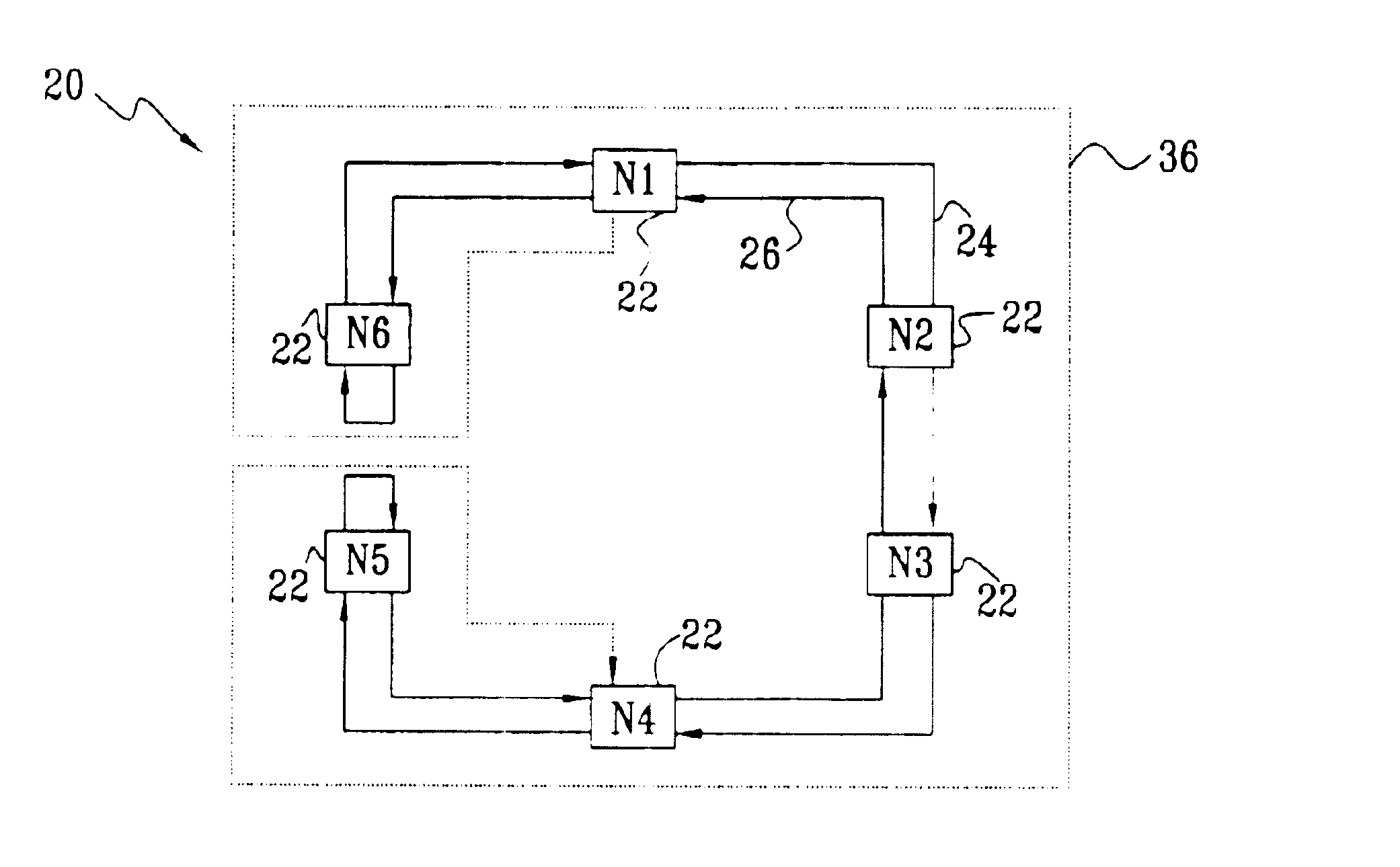
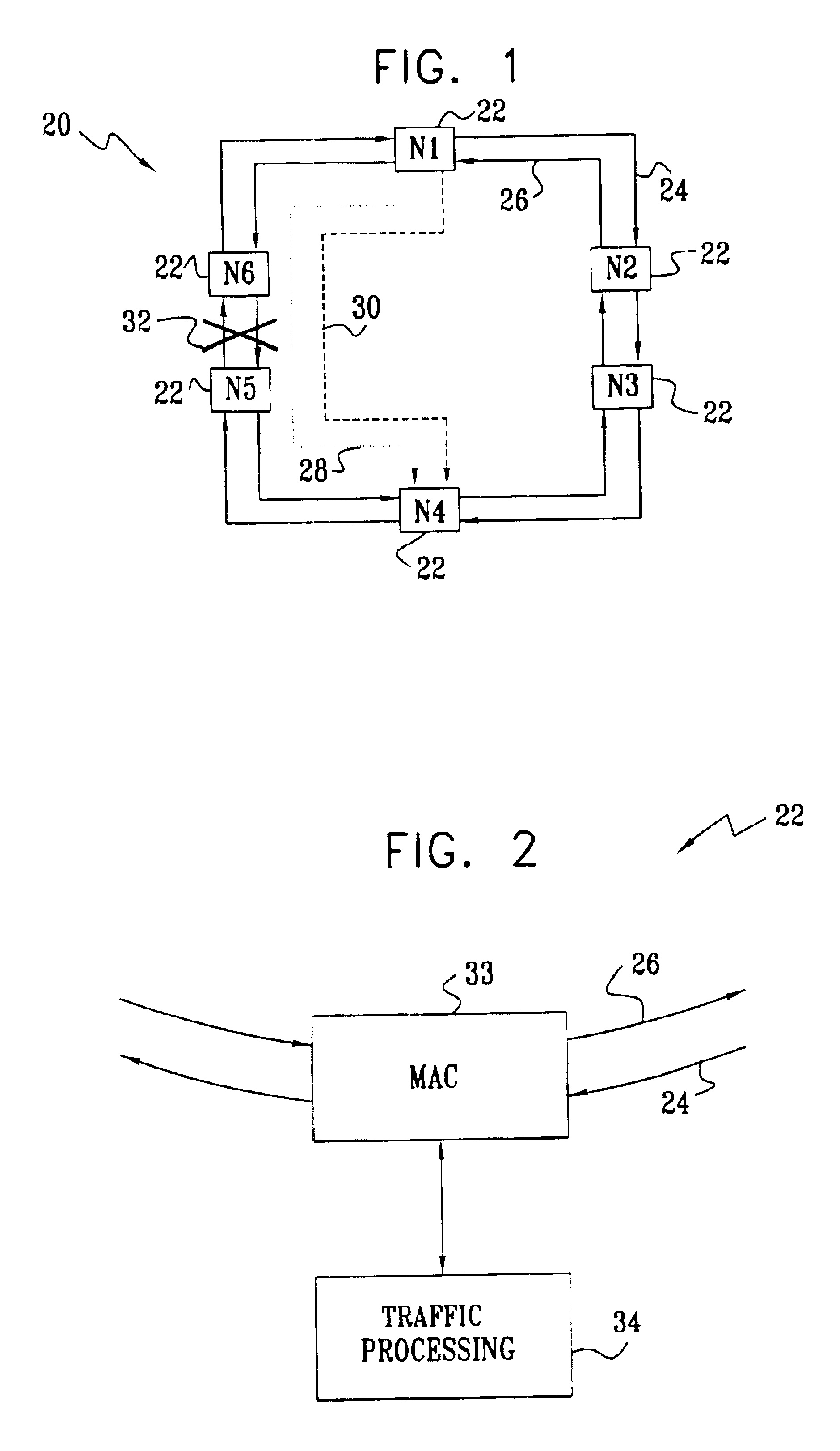
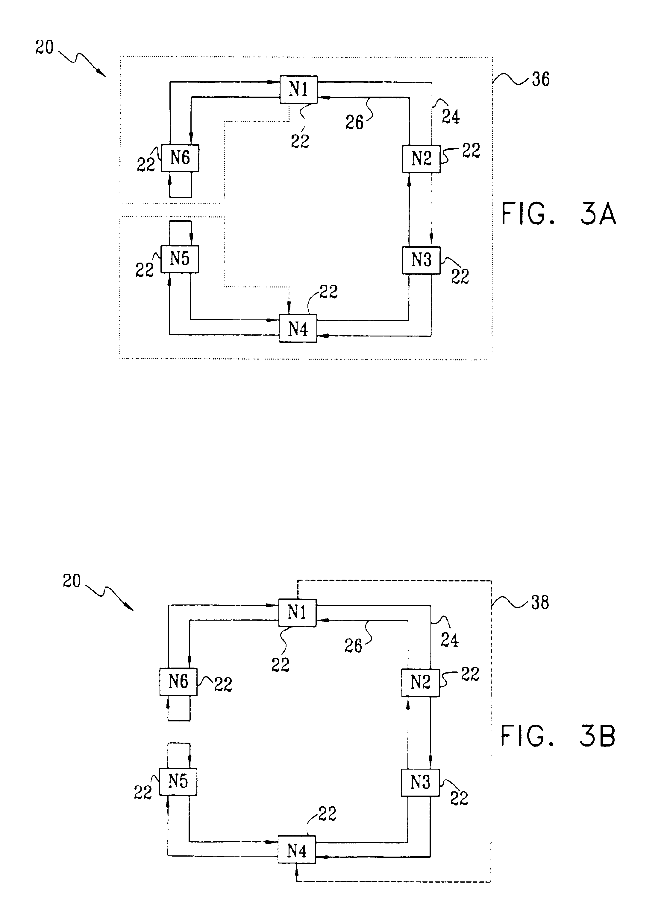
[0037]FIG. 1 is a block diagram that schematically shows a packet ring network 20, in accordance with a preferred embodiment of the present invention. Network 20 comprises nodes 22, marked N1 through N6, which are mutually connected by bidirectional communication media, such as optical fibers or conductive wires. The nodes typically comprise switching equipment, and serve as either access points or gateways to other networks (aggregation points). The communication media in network 22 are configured to define an outer ring 24, over which packets are conveyed between the nodes in a clockwise direction, and an inner ring 26, over which the packets are conveyed in a counterclockwise direction. As noted above, however, the designations of “inner,”“outer,”“clockwise” and “counterclockwise” are arbitrary and are used here simply for convenience and clarity of explanation. Furthermore, the designation and number of nodes in network 20 are chosen here by way of example, and the network may, ...


PUM


Abstract

A method for fault protection in a bidirectional ring network includes transmitting first and second flows of packets around the bidirectional ring network while defining the first flow as a wrapping flow and the second flow as a non-wrapping flow. Upon detection by a node in the network that a segment of the network proximal to the node has failed, the packets in the first flow are wrapped at the node between clockwise and counterclockwise directions on the network so as to avoid the failed segment, while the packets in the second flow are not wrapped.

Description

CROSS-REFERENCE TO RELATED APPLICATION[0001]This application claims the benefit of U.S. Provisional Patent Application No. 60 / 281,232, filed Apr. 2, 2001, which is incorporated herein by reference.FIELD OF THE INVENTION[0002]The present invention relates generally to network communication systems and protocols, and specifically to methods of fault protection in packet-switched networks.BACKGROUND OF THE INVENTION[0003]Network ring topologies are gaining in popularity, particularly in Internet Protocol (IP) networks. Such networks enable carriers to offer large bandwidth to users in a cost-effective manner, since each node in the network needs only two interfaces, rather than having to maintain a separate interface for each of the other nodes as in a mesh network. Ring networks also lend themselves to fast rerouting in the event of network failures, since two alternative routes—in clockwise and counterclockwise directions—are generally available for connecting any two nodes on the ri...

Claims


Application Information

Patent Timeline
IPC IPC(8): H04L1/22H04L12/437
CPCH04L12/437H04L1/22
Inventor BRUCKMAN, LEON
Owner RING PROTECTION LLC
Why Eureka
Eureka Blog
Learn More