Method and apparatus for optimized centralized critical control architecture for switchgear and power equipment

a critical control and switchgear technology, applied in the field of electric switchgear, can solve the problems of over-current condition, increased equipment size, and complex switching operations used

Inactive Publication Date: 2005-05-10
ABB (SCHWEIZ) AG
View PDF230 Cites 93 Cited by
  • Summary
  • Abstract
  • Description
  • Claims
  • Application Information

AI Technical Summary

Benefits of technology

[0002]This invention relates generally to electrical switchgear and more particularly, to a method and apparatus for protecting, monitoring, and controlling the electrical switchgear.

Problems solved by technology

Similar switchgear may also be used within an electric utility transmission system and a plurality of distribution substations, although the switching operations used may be more complex.
The failure of the monitoring system to record the system shutdown may mislead an operator to believe that an over-current condition has not occurred within the power distribution system, and as such, a proper corrective action may not be initiated by the operator.
As such, the control logic may undesirably attempt to connect the faulted circuit to an alternate source, thereby restoring the over-current condition.
In addition to the potential increase in operational defects which may occur using such devices, the use of multiple devices and interconnecting wiring associated with the devices may cause an increase in equipment size, an increase in the complexity of wiring the devices, and / or an increase in a quantity of devices installed.

Method used


Image

  • Method and apparatus for optimized centralized critical control architecture for switchgear and power equipment
  • Method and apparatus for optimized centralized critical control architecture for switchgear and power equipment
  • Method and apparatus for optimized centralized critical control architecture for switchgear and power equipment

Examples


Embodiment Construction

[0016]As used herein, an element or step recited in the singular and preceded with the word “a” or “an” should be understood as not excluding plural said elements or steps, unless such exclusion is explicitly recited. Furthermore, references to “one embodiment” of the present invention are not intended to be interpreted as excluding the existence of additional embodiments that also incorporate the recited features.

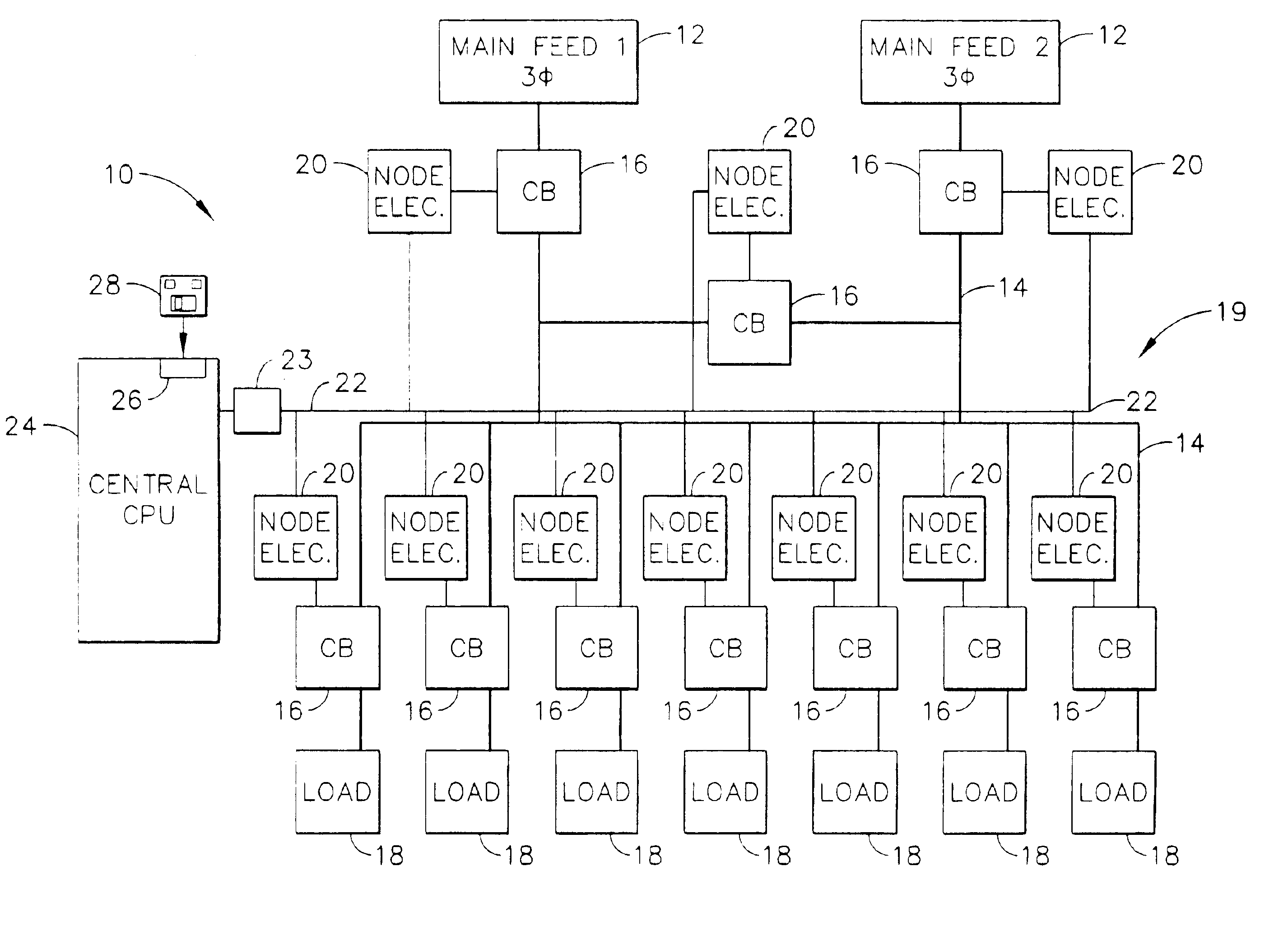
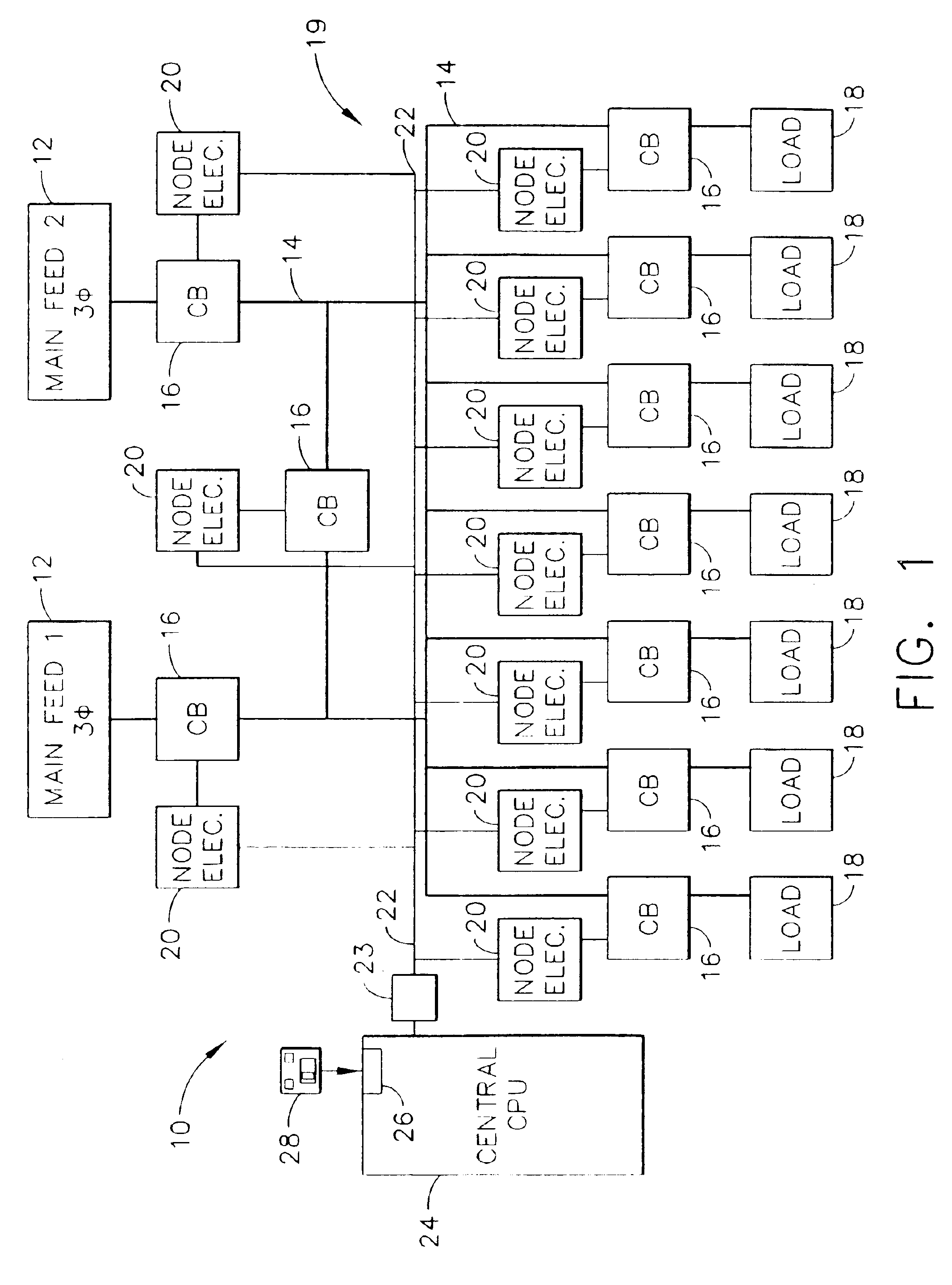
[0017]FIG. 1 illustrates an exemplary schematic illustration of a power distribution system 10, used by an industrial facility for example. In an exemplary embodiment, system 10 includes at least one main feed system 12, a power distribution bus 14, a plurality of power circuit switches or interrupters, also referred to herein as a circuit breakers (CB) 16, and at least one load 18, such as, but not limited to, motors, welding machinery, computers, heaters, lighting, and / or other electrical equipment.

[0018]In use, power is supplied to a main feed system 12, i.e. a switchbo...


PUM


Abstract

A method of monitoring and controlling a power distribution system is provided. The power distribution system includes a plurality of circuit breakers, a plurality of node electronic units, and wherein each associated circuit breaker is electrically coupled with each respective node electronic unit. The system also includes at least one digital network, and at least one central control processing unit (CCPU) wherein each CCPU includes a first power system global information set, and each CCPU is communicatively coupled to the plurality of node electronic units. The method includes transmitting at least one digital message from each node electronic unit to each CCPU over a respective network, determining an operational state of the power distribution system from the digital message, and transmitting at least one multicast message from each CCPU to each node electronic unit such that the circuit breakers are operable from each CCPU.

Description

CROSS REFERENCE TO RELATED APPLICATIONS[0001]This application is related to U.S. Patent Application No. 60 / 359,544 filed on Feb. 25, 2002 for “Integrated Protection, Monitoring, and Control” the content of which is incorporated in its entirety herein by reference. This application is also related to U.S. Patent Application No. 60 / 438,159 filed on Jan. 6, 2003 for “Single Processor Concept for Protection and Control of Circuit Breakers in Low-Voltage Switchgear” the content of which is incorporated in its entirety herein by reference.BACKGROUND OF THE INVENTION[0002]This invention relates generally to electrical switchgear and more particularly, to a method and apparatus for protecting, monitoring, and controlling the electrical switchgear.[0003]In an industrial power distribution system, power generated by a power generation company may be supplied to an industrial or commercial facility wherein the power may be distributed throughout the industrial or commercial facility to various...

Claims


Application Information

Patent Timeline
Patent Type & Authority Patents(United States)
IPC IPC(8): G06F1/12H02J13/00H02H7/26H02H1/00H02H3/00H02H3/05H04L12/24G06F3/05H01H83/20H02H7/30H02J3/00H04L1/00H04L12/26
CPCG06F1/12H01H83/20H02H3/006H02H7/261H02H7/262H02H7/263H02H7/30H02J3/00H02J3/005H02J13/001H02J13/002H02J13/0024H02J13/0055H02J13/0062H02J13/0079H02J13/0086H04J3/0658H04L1/0002H04L1/0018H04L12/2602H04L43/00H04L47/10H02J3/12G06F3/05Y04S40/125H01H2300/03H02H1/0061H02H3/05H02J13/0072H02J2003/001H02J2003/007H02J2003/146H04J3/0661H04L41/0253H04L43/06H04L43/0817Y02B90/224Y02B90/2615Y02B90/2623Y02B90/2638Y04S10/40Y04S20/14Y04S20/224Y04S40/121Y04S40/122Y04S40/124Y04S40/168Y02B70/3241Y02B60/31Y04S20/227Y02B90/2646H02J3/001H02J2310/64H02J13/00009H02J13/00012H02J13/00018H02J13/00001H02J13/00007H02J2203/20H02J13/00016H02J13/00028H02J13/00034H02J13/00036H02J13/0004Y02B90/20Y02D30/50Y02P80/10Y04S20/222Y04S40/00Y04S50/10Y02B70/3225H02J3/007Y02B70/30Y04S20/20
Inventor BERKCAN, ERTUGRULSEXTON, DANIEL WHITEEVANS, SCOTT CHARLESPEARLMAN, MARC ROBERTANDARAWIS, EMAD ANDARAWISSCHNORE, JR., AUSTARS RAYMONDSEALING, CHARLES SCOTTPREMERLANI, WILLIAM JAMESWANG, CHANGTINGTOPKA, TERRY MICHAEL
Owner ABB (SCHWEIZ) AG
Why Eureka
Try Eureka