Optical compensatory sheet, liquid-crystal display and elliptical polarizing plate employing same
a technology of optical compensatory sheet and liquid crystal display, which is applied in the direction of polarizing elements, thin material processing, instruments, etc., can solve the problems of insufficiently ensuring the tilt angle of the viewing angle of discotic liquid crystal molecules is not sufficiently broadened, and the leakage of optical components is found. , to achieve the effect of broadening the viewing angle of discotic liquid crystal molecules, broadening the viewing angle, and increasing the tilt angle of dis
- Summary
- Abstract
- Description
- Claims
- Application Information
AI Technical Summary
Benefits of technology
Problems solved by technology
Method used
Image


Examples
example 1
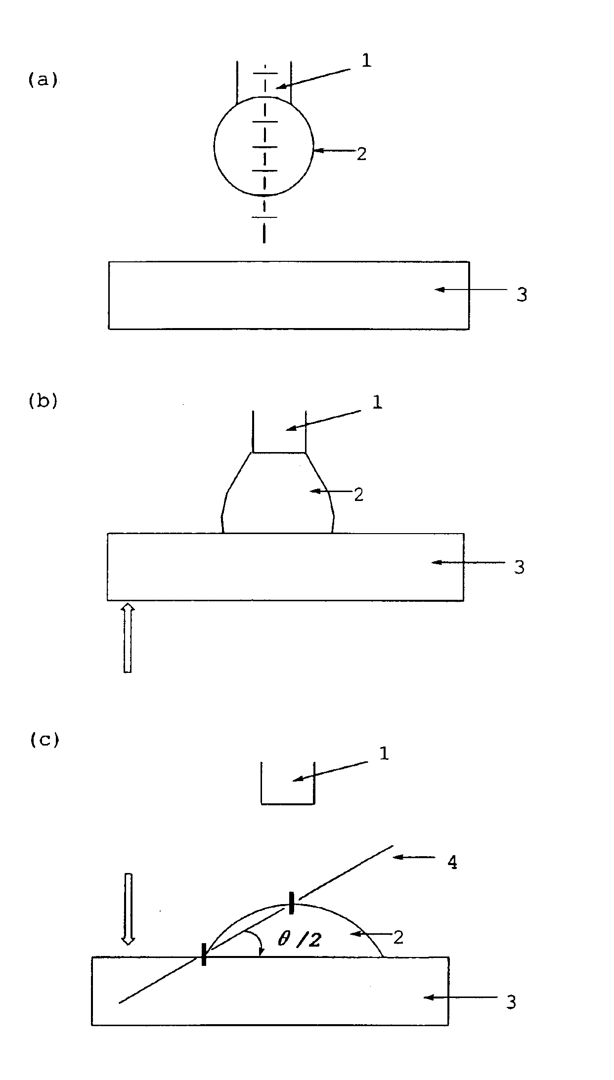
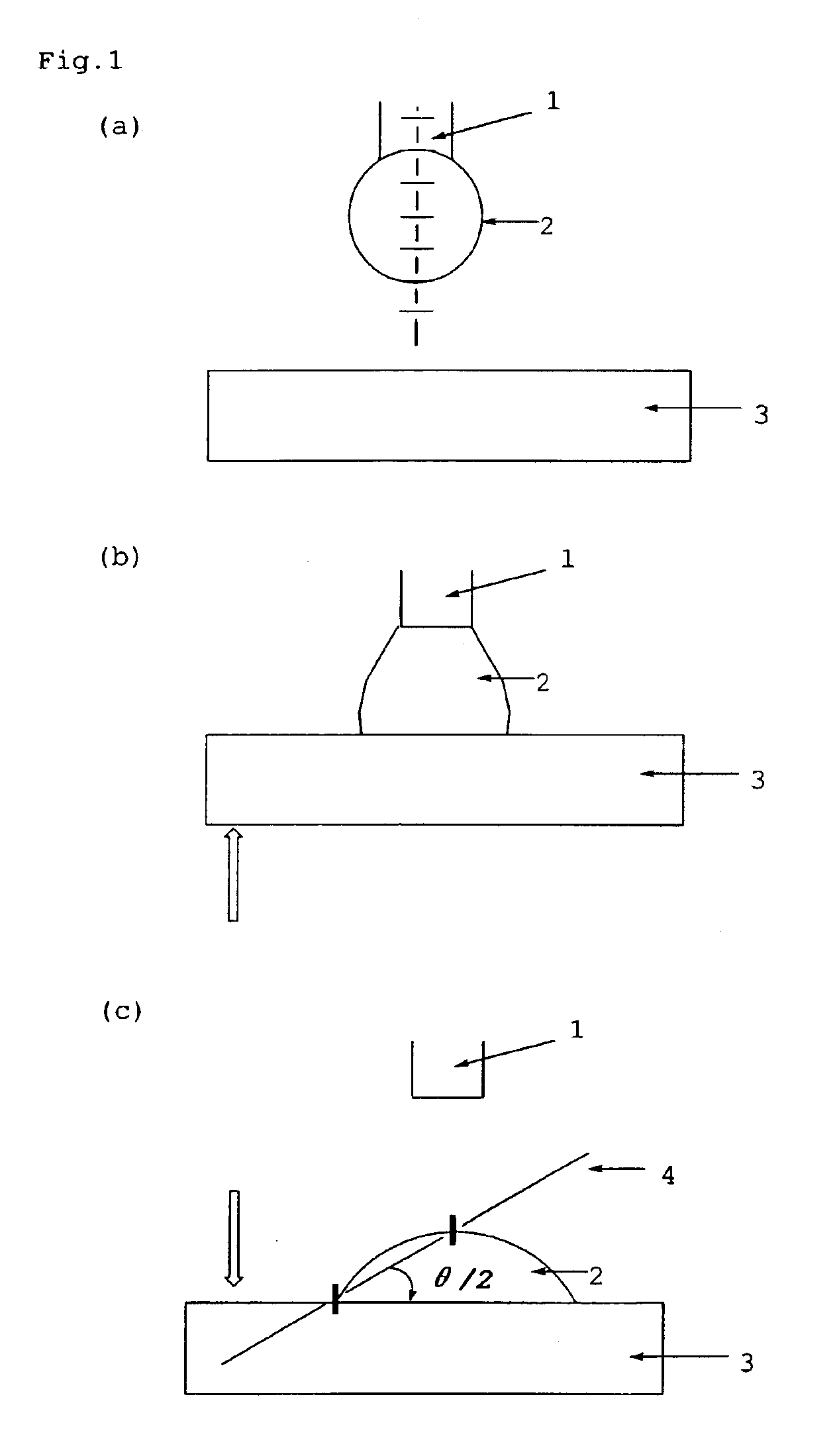
(Measurement of an Air Interface Polarity of an Optically Anisotropic Layer)
[0118]2 g of a polymer shown bellow was dissolved in mixed solvent of 36 g of pure water and 12 g of methyl alcohol, and the solution was applied to a transparent glass substrate. After drying at 100° C. for 2 minutes to form a layer, an alignment layer was formed by rubbing treatment of the layer with tucked in by 0.2 μm. The thickness of the alignment layer was 0.5 μm.
[0119]Polymer for production of an alignment layer
[0120]The polymerization degree of the polymer was 300 and the molar ration x:y:z was 1.7:86.3:12.
[0121]The alignment layer was cut into the dimension of 2 cm×2.5 cm and the coating liquid containing following components was applied to the alignment layer by spin coating method with 2000 rpm. An optically anisotropic layer having a thickness of 1.5 μm was formed on the alignment layer.
[0122]
Coating liquid of optically anisotropic layerDiscotic liquid-crystal compound90weight partsdescribed be...
examples 2 to 5 , 1
Examples 2 to 5, 1′ and 2′
[0125]Various optically anisotropic layers were formed in the same manner as the example 1, except that various compounds represented by the formula (I) shown in Table 1 were respectively used with the same mixed ration and the amount in place of Compound No. 19. The air interface polarities of the formed optically anisotropic layers were measured in the same manner as the example 1. The results are shown in Table 1.
[0126]
TABLE 1AirContact Angleinterface(deg)Surface Free EnergyExamplecontrolmethylene(mN / m)PolarityNo.agentwateriodideγsdγspγγsp / γsdPadd / Pnon-add*1No.I-1929.521.231.616.448.00.521.572No.I-2025.830.811.143.054.13.8711.703No.I-2128.733.317.825.843.71.444.364No.I-2321.336.013.641.555.13.059.245No.I-8124.734.216.033.649.62.106.36 1′Compound(A)30.515.038.012.550.50.331.00 2′non30.515.038.012.550.50.33—*Padd means a polarity of the optically anisotropic layer added the agent. *Pnon-add means a polarity of an optically anisotropic layer not added the a...
example 6
(Preparation of the Transparent Support)
[0129]The following components were charged to a mixing tank and stirred with heating to prepare a cellulose acetate solution (dope).
[0130]
Composition of cellulose acetate solution compositionCellulose acetate with a 60.9 percent100weight partsdegree of acetationTriphenyl phosphate6.5weight partsBiphenyldiphenyl phosphate5.2weight partsRetardation enhancer (1) described below0.1weight partRetardation enhancer (2) described below0.2weight partMethylene chloride310.25weight partsMethanol54.75weight parts1-Butanol10.95weight partsRetardation enhancer (1) Retardation enhancer (2)
[0131]The dope obtained was made to flow out of a nozzle onto a drum cooled to 0° C. It was peeled off while having a solvent content of 70 weight percent, the two edges of the film in the transverse direction were fixed with a pin tenter, and in the area where the solvent content was from 3 to 5 weight percent, the film was dried while maintaining a spacing yielding a st...
PUM
| Property | Measurement | Unit |
|---|---|---|
| mean tilt angle | aaaaa | aaaaa |
| temperature | aaaaa | aaaaa |
| thickness | aaaaa | aaaaa |
Abstract
Description
Claims
Application Information
 - R&D
- Intellectual Property
- Life Sciences
- Materials
- Tech Scout
- Unparalleled Data Quality
- Higher Quality Content
- 60% Fewer Hallucinations
Browse by: Latest US Patents, China's latest patents, Technical Efficacy Thesaurus, Application Domain, Technology Topic, Popular Technical Reports.
© 2025 PatSnap. All rights reserved.Legal|Privacy policy|Modern Slavery Act Transparency Statement|Sitemap|About US| Contact US: help@patsnap.com