
Antilock brake systems employing a sliding mode observer based estimation of differential wheel torque

a differential wheel and antilocking technology, applied in the field of antilocking brake systems, can solve the problems of limiting the ability of the '951 patent method to function properly in real-time braking situations, the angular speed of the nose wheel is only a very noisy measurement of the true aircraft velocity, and the approach is very complex mathematically, so as to achieve the effect of simple implementation

Inactive Publication Date: 2005-05-10
SMO GRP
View PDF16 Cites 58 Cited by
  • Summary
  • Abstract
  • Description
  • Claims
  • Application Information

AI Technical Summary

Benefits of technology

[0018]We have realized that, since the underlying mathematical model for differential wheel torque ΔT is only partially known, a sliding mode observer or SMO would be the ideal mathematical tool for estimating the net or differential wheel torque ΔT using measurements of wheel speed only. We compare an SMO-based estimate of differential wheel torque Δ{circumflex over (T)} to a threshold differential wheel torque, ΔTthreshold, and derive a braking control signal on / off brake control commands from the results of the comparison. When the vehicle brakes are applied by the operator, the braking control signal periodically interrupts the braking and optionally modulates the braking force during wheel lock-up depending on the results of the comparison of the estimate of differential wheel torque ΔT to a threshold differential wheel torque, ΔTthreshold, so as to optimize wheel slip during braking. The SMO-based method of our invention is extremely simple to implement within an existing embedded ABS microprocessor or vehicle computer and employs currently available, inexpensive, on-board sensor inputs. The SMO-based ABS method of our invention instantly self-adapts over a broad range of possible optimal slip S* values to provide near optimal braking in real time.
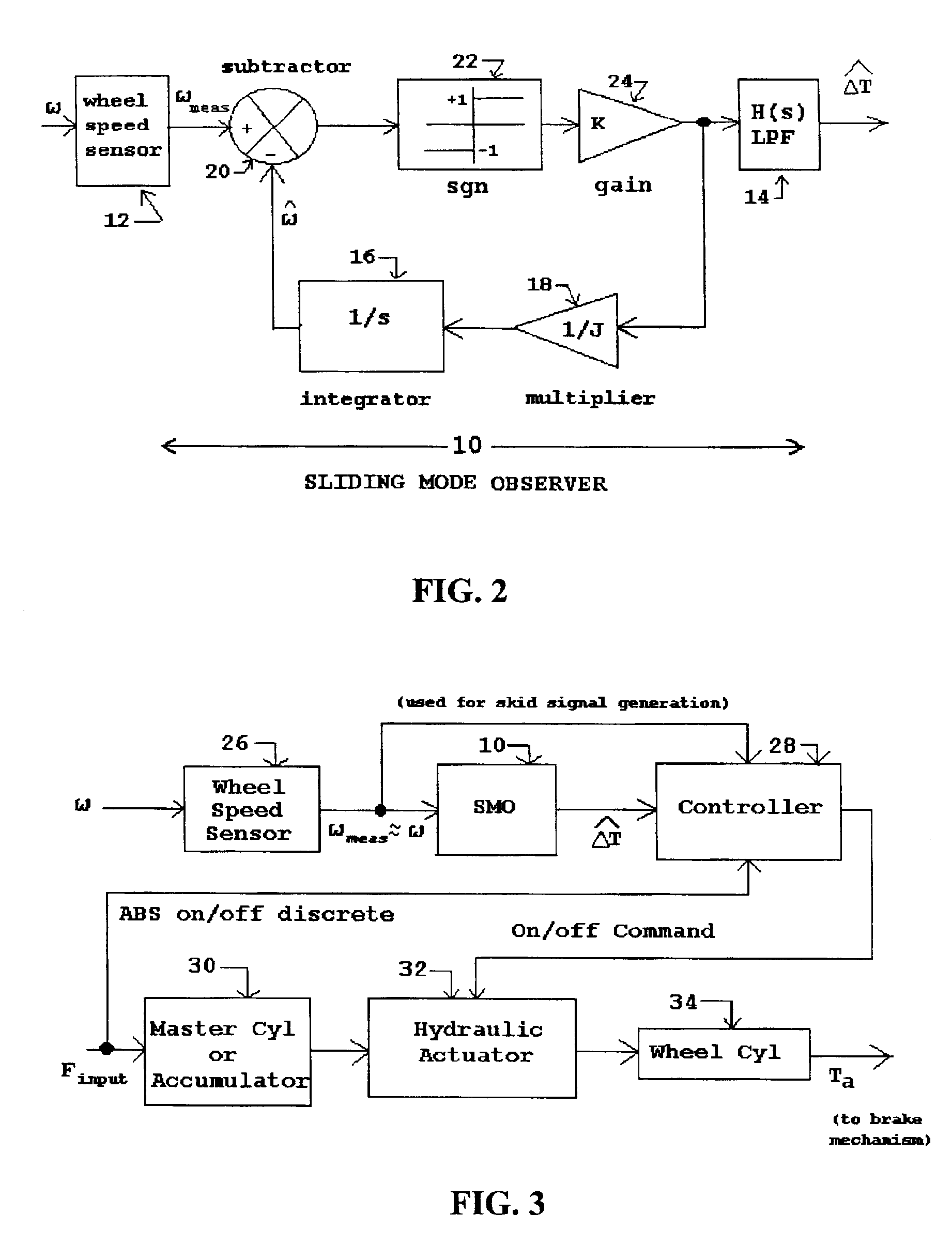
[0019]The sliding mode observer estimates the net or differential wheel torque ΔT which corresponds to drag torque Tb less applied brake torque Ta using only the measured wheel angular speed ωmeas. With a good wheel sensor ωmeas is almost exactly the same as the (true) wheel angular speed ω appearing in equation (1). For simplicity in all the following discussion and mathematics we shall therefore drop the subscript “measured” and use the single symbol ω for both measured and true instantaneous wheel angular speed. However, we shall always indicate which is meant in the associated text. The SMO-based method of our invention is extremely simple to implement within an existing embedded ABS microprocessor or vehicle computer and employs currently available, inexpensive, on-board sensor inputs. The SMO-based ABS method of our invention instantly self-adapts over a broad range of possible optimal slip, S*, values to provide near optimal braking in real time.

Problems solved by technology

Unfortunately, the nose wheel angular speed is only a very noisy measurement of the true aircraft velocity during the landing roll.
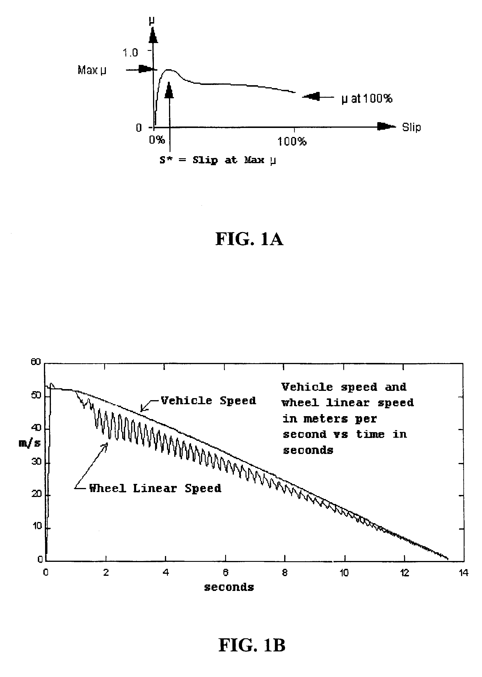
The fundamental problem with such approaches is that optimal slip S* is not really a known constant but rather varies from under 0.1 to over 0.20, dependent on ground surface conditions, although most often in the range 0.11 to 0.15 (thus partially justifying the frequently used value of S*=0.13 mentioned earlier).
However, the mathematical complexity associated with such a mathematical estimation procedure might limit the ability of the '951 patent method to function properly in real-time braking situations.
Rudd attempts to actually estimate S* and then command a pressure to the brake actuator that will continuously drive instantaneous slip S to optimal slip S*, but his approach is very complex mathematically involving an 8-state Kalman filter solution that must be repeated many, many times per second.
Furthermore, while wheel angular speed sensors are cheap, the velocity and acceleration sensors required by Rudd in his preferred embodiment are usually associated with expensive inertial or air data systems.

Method used


Image

  • Antilock brake systems employing a sliding mode observer based estimation of differential wheel torque
  • Antilock brake systems employing a sliding mode observer based estimation of differential wheel torque
  • Antilock brake systems employing a sliding mode observer based estimation of differential wheel torque

Examples


first embodiment

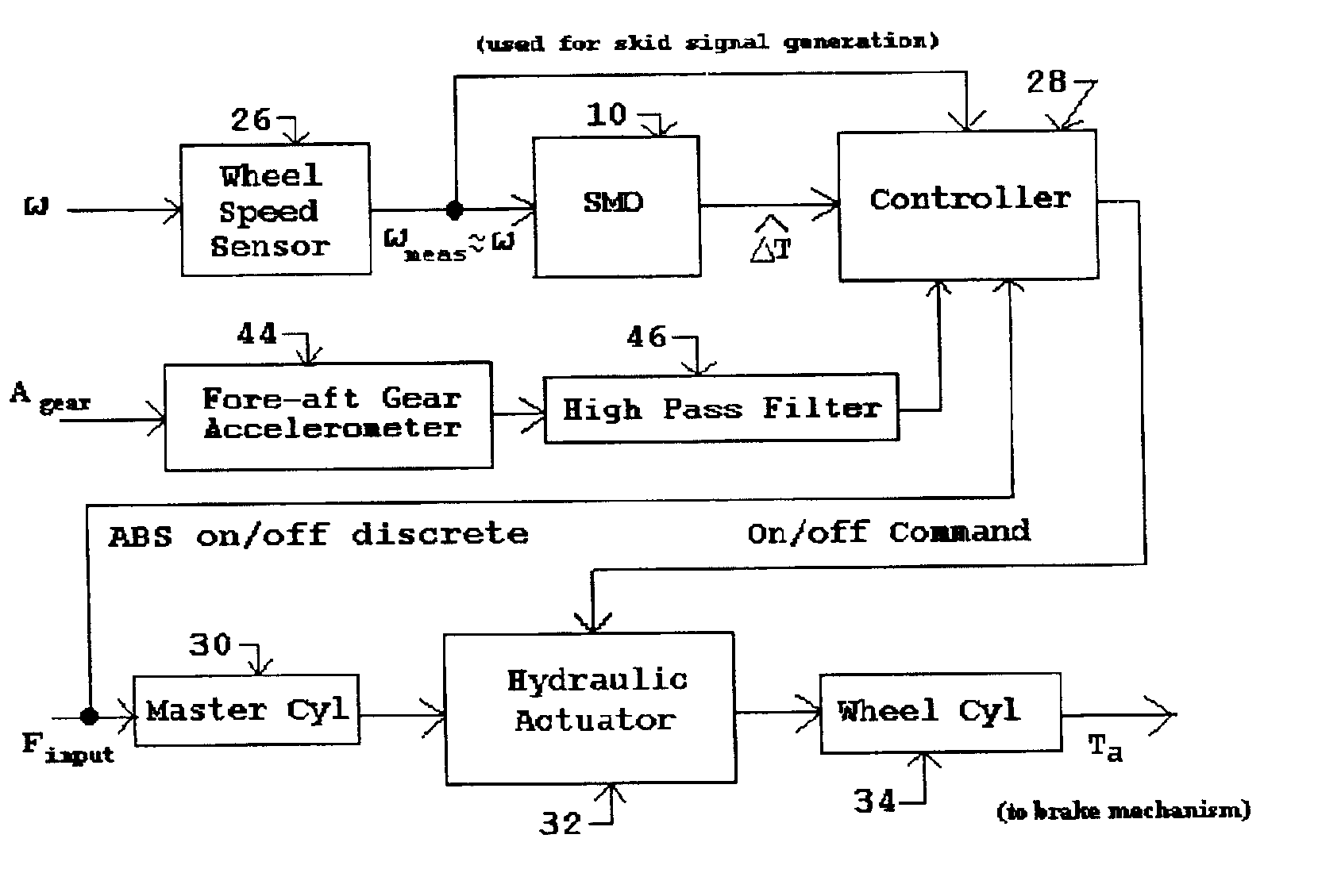
[0051]When the ABS controller 28 is not active, the resultant output hydraulic pressure from the master cylinder 30 is transmitted through the hydraulic actuator 32 in direct proportion to the input force Finput and without further attenuation to a wheel cylinder 34. The latter produces the applied brake torque Ta, typically by a mechanical brake mechanism coupled to and moved by the piston of the wheel cylinder 34. When the ABS controller 28 is active, the hydraulic actuator 32 functions to abruptly reduce the applied hydraulic pressure to the wheel cylinder 34 in accordance with on / off brake control signal (BCS) commands from the ABS controller 28 when the latter determines, during braking, that a skid condition exists based upon the measured wheel speed ω as will be described in more detail below. In this first embodiment, the reduction in applied hydraulic pressure corresponding to the BCS is either none (zero), whereby the full hydraulic pressure from the master cylinder 28 is ...

second embodiment

[0084]Third Preferred Embodiment: A third preferred embodiment of the present SMO-based ABS of the present invention is depicted in FIG. 5, wherein the brake mechanism incorporates an electro-mechanical actuator 40 instead of the hydraulic actuator 32 of the first and Such an electro-mechanical actuator 40 typically consists of an electric motor that moves the brake pad or caliper assembly into contact with the brake disk rotor stack and thereby applies an applied brake force, Fa, and brake torque Ta to decrease the wheel angular velocity or wheel speed ω.

[0085]In this embodiment, the brake pedal force Finput is measured by a sensor 38, typically some form of strain gauge. When the ABS is not active, the measured pedal force Finput alone is used to generate a target braking command in the ABS controller 28. The ABS controller 28 therefore ignores the wheel speed measurement ω and the estimate of differential wheel torque ΔT shown in FIG. 5. The ABS controller 28 simply generates th...


PUM


Abstract

Improved methods and systems for controlling hydraulically or electrically actuated anti-lock brake systems (ABS) on air and land vehicles requiring only measurement of wheel angular speed although brake torque measurements can also be employed if available. A sliding mode observer (SMO) based estimate of net or different wheel torque (road / tire torque minus applied brake torque) derived from the measured wheel speed is compared to a threshold differential wheel torque derived as a function of a “skid signal” also based on wheel speed only to generate a braking control signal. The braking control signal can be employed to rapidly and fully applying and releasing the brakes in a binary on-off manner and, as an additional option, possibly modulating the maximum available brake hydraulic pressure or electrical current when the brakes are in the “on” state in a continuous manner. In the case of the basic on-off component of braking, the brakes are released when the estimate of differential wheel torque is less than the threshold differential wheel torque (i.e. for relatively high values of brake torque), and the brakes are applied fully when the estimate of differential wheel torque is greater than or equal to the threshold differential wheel torque. For aircraft landing gear applications, a fore-aft accelerometer mounted on the landing gear can be used to suppress nonlinear gear displacement oscillations commonly called gear walk in the direction of wheel roll.

Description

RELATED APPLICATIONS[0001]This application claims priority to provisional U.S. application Ser. No. 60 / 266,701 filed Feb. 6, 2001, “METHOD FOR CONTROLLING ANTILOCK BRAKE-SYSTEMS ON AIRCRAFT AND LAND VEHICLES EMPLOYING A SLIDING MODE OBSERVER BASED ON ESTIMATION OF DIFFERENTIAL WHEEL TORQUE”, William B. Ribbens and Ronald J. Fredricks.FIELD OF THE INVENTION[0002]The present invention pertains to anti-lock brake systems (ABS) employed on aircraft and land vehicles, and particularly to an improved ABS and method of operating same employing a sliding mode observer (SMO) incorporated into an ABS algorithm requiring only measurement of wheel angular speed, and optionally employing brake torque measurement if available.BACKGROUND OF THE INVENTION[0003]Brake systems, whether for aircraft or land vehicles, function by applying a retarding torque to the braked wheels of the vehicle that is in a direction opposite to the rotational direction of the wheel as the vehicle moves across a road or r...

Claims


Application Information

Patent Timeline
IPC IPC(8): B64C25/00B60T8/1761B64C25/46B60T8/17
CPCB64C25/46B60T8/17616
Inventor RIBBENS, WILLIAM B.FREDRICKS, RONALD J.
Owner SMO GRP
Learn More