Integrated single and dual television tuner having improved fine tuning

a technology of integrated single and dual television tuners and fine tuning, which is applied in the field of television tuners, can solve the problems of multiple loop frequency, limited fine tuning, and large volume of the tuner, and achieve the effect of fine tuning the tuner

Inactive Publication Date: 2005-05-03
ATI TECH INC
View PDF20 Cites 38 Cited by
  • Summary
  • Abstract
  • Description
  • Claims
  • Application Information

AI Technical Summary

Benefits of technology

[0013]Therefore, in accordance with a further aspect of the present invention, there is provided a dual conversion television tuning circuit for tuning a television channel in a received radio frequency signal, including first and second frequency synthesizers; a first mixer, to mix the channel, with a first mixing signal from the first frequency synthesizer and thereby frequency shift the channel to a first frequency; and a bandpass filter coupling an output of the first mixer to an input of a second mixer. The second mixer mixes the channel with a second mixing signal from the second frequency synthesizer and thereby translates the channel to an intermediate frequency. At least one of the first and second synthesizer is formed using a fractional-N frequency synthesizer, comprising a single controllable oscillator, to allow fine tuning of said tuning circuit.
[0014]In accordance with yet another aspect of the present invention, there is provided a method of tuning a television tuner, including synthesizing a mixing signal using a fractional-N frequency synthesizer; providing the mixing signal to a mixer thereby fine tuning the tuner.
[0016]Accordingly, in accordance with one more aspect of the present invention, there is provided a method of tuning two co-located television tuners, including synthesizing a first mixing signal using a first fractional-N frequency synthesiser; synthesizing a second mixing signal using a second fractional-N frequency synthesiser; providing the first and second mixing signals to first and second mixers, respectively, thereby fine tuning said two tuners.

Problems solved by technology

Accordingly, tuners had traditionally been quite bulky and expensive to produce.
Multiple loop frequency synthesizers, however, typically only allow for limited fine tuning.
Clearly, the more such VCOs that are used, the more difficult it is to prevent the interference of spurious signals.
Current integration techniques, however, typically do not entirely prevent these multiple PLLs and VCOs from interfering with each other.

Method used


Image

  • Integrated single and dual television tuner having improved fine tuning
  • Integrated single and dual television tuner having improved fine tuning
  • Integrated single and dual television tuner having improved fine tuning

Examples


Embodiment Construction

[0028]For clarity of description, a conventional television tuning circuit is described with reference to FIGS. 1-3. Thereafter, tuning circuits exemplary of embodiments of the present are described with reference to FIGS. 4-8.

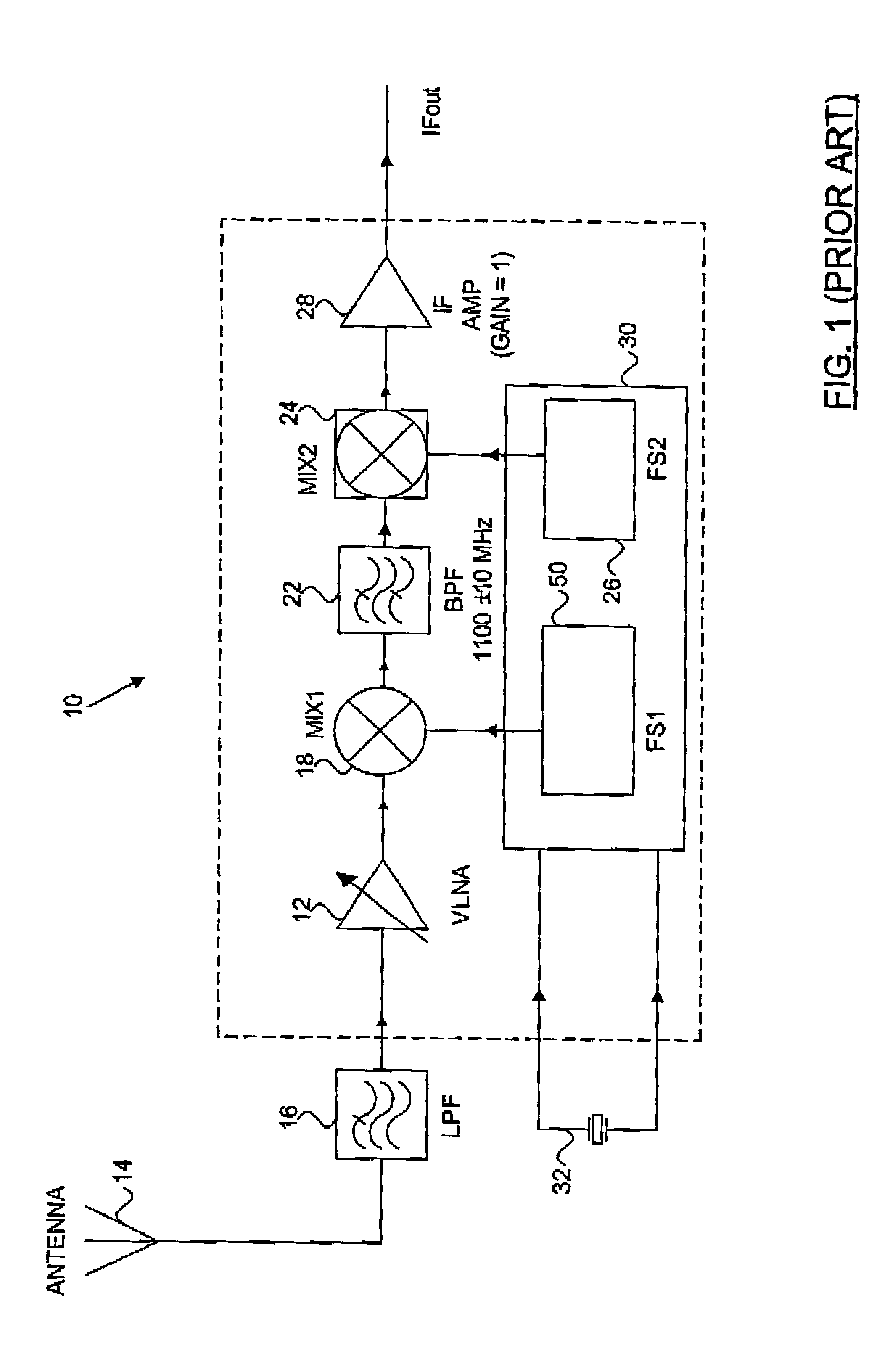
[0029]FIG. 1 illustrates a conventional television tuning circuit 10. Television tuning circuit 10 is a conventional dual conversion RF receiver, including a variable gain, low noise amplifier (“VLNA”) 12 taking as input an RF signal received from antenna 14, and filtered by lowpass filter 16. Output of VLNA 12 is provided to a mixer 18, where it is mixed with the output of a frequency synthesizer 50 of a frequency synthesizer block 30. This shifts a channel to be tuned to a first intermediate frequency. A bandpass filter 22 having a centre frequency at about this first intermediate frequency receives the output of mixer 18 and filters a lower or higher sideband of the mixed signal. Example bandpass filter 22 may have a fixed bandpass frequency, typically of 1...


PUM


Abstract

Improved television tuning circuits are disclosed. An example tuning circuit includes a fraction-N frequency synthesizer facilitating fine tuning. This tuning circuit may be formed using relatively few independent oscillators. The tuning circuit lends itself to the formation of an tuning circuit on an integrated circuit substrate. As well, this tuning circuit may be used to form a dual tuner tuning circuit integrated on a single integrated circuit substrate.

Description

FIELD OF THE INVENTION[0001]The present invention relates to television tuners, and more particularly to a tuning circuit including one or more tuners having improved fine tuning, that may be integrated on a single integrated circuit substrate.BACKGROUND OF THE INVENTION[0002]Television tuning circuits have been known, developed and improved since the advent of the television. Such tuning circuits convert received high frequency radio frequencies to an intermediate frequency (“IF”). Historically, such tuning circuits were embodied in tuners that formed integral parts of single purpose bulky television receivers, typically including a cathode ray tube. These tuners were usually manufactured using conventional discrete passive and active components. Accordingly, tuners had traditionally been quite bulky and expensive to produce.[0003]More recently, television receivers have formed part of smaller electronic devices such as handheld televisions, video cassette recorders (“VCR”s), and p...

Claims


Application Information

Patent Timeline
Patent Type & Authority Patents(United States)
IPC IPC(8): H03D7/00H03D7/16H03L7/197H03L7/193H03L7/23H03L7/16H04N5/44H04N5/50
CPCH03D7/161H03L7/193H03L7/1974H04N5/50H03L7/23H04N5/4446H03L7/1976H04N21/4263
Inventor DUJMENOVIC, FELIKS
Owner ATI TECH INC
Why Eureka
Try Eureka