
Material for making a conductive pattern

a conductive pattern and material technology, applied in the field of materials and a method for making a conductive pattern, can solve the problems of high fabrication cost, limited application range, low flexibility (pliability) and stretchability, and achieve the effect of increasing the surface conductivity

Inactive Publication Date: 2005-05-03
AGFA GEVAERT AG
View PDF5 Cites 10 Cited by
  • Summary
  • Abstract
  • Description
  • Claims
  • Application Information

AI Technical Summary

Benefits of technology

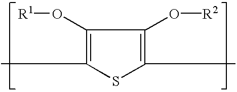
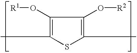
[0016]Aspects of the present invention are realized by providing a material for making a conductive pattern, the material comprising a support and a heat-differentiable element, the heat-differentiable element comprising an outermost layer containing a polyanion and an intrinsically conductive polymer and optionally a second layer contiguous with the outermost layer, characterized in that the s outermost layer and / or the optional second layer contains hydrophobic thermocoagulable latex particles in a weight ratio range with respect to the intrinsically conductive polymer in the range of 20:1 to 1:5, the hydrophobic thermocoagulable latex particles are capable upon heating of increasing the conductivity of the heated parts of the outermost layer relative to the unheated parts of the outermost layer and / or changing the removability of the heated parts of the outermost layer relative to the unheated parts of the outermost layer and the heat-differentiable element does not comprise a di- or polyhydroxy organic compound or an aprotic compound with a dielectric constant, ∈, ≧15.
[0017]Aspects of the present invention are also realized by providing a method of making a conductive pattern on a support comprising the steps of: providing the above-mentioned material for making a conductive pattern; image-wise heating the material thereby obtaining a differentiation of the surface conductivity and / or removability with a developer of the heated and the unheated areas of the outermost layer; optionally processing the material with the developer, thereby at least partially removing areas of the outermost layer optionally together with a layer contiguous therewith; and optionally treating the material with a conductivity enhancement agent to increase the conductivity of the non-removed areas of the outermost layer.

Problems solved by technology

The range of potential applications is limited, because of the high fabrication costs, the low flexibility (pliability) and stretchability as a consequence of the brittleness of the ITO layer and the glass substrate.
Such methods are cumbersome as they involve many steps and require the use of hazardous chemicals.

Method used


Image

  • Material for making a conductive pattern
  • Material for making a conductive pattern
  • Material for making a conductive pattern

Examples


example 1

[0100]In the material for making a conductive pattern of Samples I to IV, the heat-differentiable element consisted of PEDOT / PSS, LATEX01 (a polystyrene latex) and FT 248 and optionally IR01 (a compound capable of converting absorbed infrared-light into heat). Samples I to IV were produced by coating 40 mL / m2 of the dispersions given in Table 2 on support nr. 01 to a wet thickness of 40 μm to produce heat-differentiable elements with the compositions given in Table 2 after drying.

[0101]

TABLE 2composition of the coating dispersionsSAM-SAM-SAM-SAM-INGREDIENT [g]PLE IPLE IIPLE IIIPLE IVSupport nr.010101011.2% aq. PEDOT / PSS dispersion417417417417LATEX0111911960301% aqueous IR01 solution—2002002005% by wt. aq. sol. of FT 2485555deionized water459259318348PEDOT / PSS [mg / m2]200200200200LATEX01 [mg / m2]10001000500250IR01 [mg / m2]—808080FT 248 [mg / m2]10101010LATEX01 / PEDOT weight ratio17.3217.328.664.33

Heating in a Drying Cupboard

The materials of Samples I, II, III and IV were heated in a drying...

example 2

[0112]In the material for making a conductive pattern of Samples V to XI, the heat-differentiable element consisted of PEDOT / PSS, LATEX01 (a polystyrene latex) and FT 248 and optionally polyacrylic acid, poly(vinyl alcohol) and IR01 (an infra-red absorber capable of converting absorbed infrared-light into heat). Samples V to XI were produced by coating 40 mL / m2 of the dispersions given in Table 9 on support nr. 01 to a wet thickness of 40 μm. After drying Samples V to XI had the compositions also given in Table 9.

[0113]

TABLE 9composition of the coating dispersionsSAMPLEVVIVIIVIIIIXXXIINGREDIENT [g]Support nr.010101010101011.2% aq. PEDOT / PSS disp.417417417417417417417LATEX01606060 156030151.5% aqueous PAA solution—100—————1% aqueous IR01 solution200200200200———5% aqueous PVA solution——50————50 g / L FT 2485555555deionized water318218268363518548563INGREDIENT [mg / m2]PEDOT / PSS200200200200200200200LATEX01500500500125500250125PAA—60—————PVA——100————IR0180808080———FT 24810101010101010LATEX0...

example 3

[0122]In the material for making a conductive pattern of Samples XII to XVIII, the heat-differentiable element consisted of PEDOT / PSS, a polystyrene or poly(methyl methacrylate) (PMMA) latex and FT 248. Samples XII to XVIII were produced by coating 40 mL / m of the dispersions given in Table 13 on support nr. 01 to a wet thickness of 40 μm. After drying Samples XII to XVIII had the compositions also given in Table 13. The figures in brackets are the particle sizes of the latex in nm.

[0123]

TABLE 13composition of the coating dispersionsSAMPLEINGREDIENT [g]XIIXIIIXIVXVXVIXVIIXVIIISupport nr. 01 01 01 01 01 01 011.2% ag. PEDOT / PSS disp.417417417417417417417LATEX01 60——————LATEX02— 60—————LATEX03—— 60————LATEX04——— 63———LATEX05———— 62—LATEX06————— 61—LATEX07—————— 6150 g / L FT 248 5 5 5 5 5 5 5deionized water518518518515516517517PEDOT / PSS [mg / m2]200200200200200200200PS latex [mg / m2]500( )500(68)—————PMMA latex [mg / m2]——500(68)500(54)500(52)500(49)500(64)FT 248 [mg / m2] 10 10 10 10 10 10 10LA...


PUM

PropertyMeasurementUnit
temperaturesaaaaaaaaaa
temperatureaaaaaaaaaa

Abstract

A material for making a conductive pattern, the material comprising a support and a heat-differentiable element, the heat-differentiable element comprising an outermost layer containing a polyanion and an intrinsically conductive polymer and optionally a second layer contiguous with the outermost layer, characterized in that the outermost layer and / or the optional second layer contains hydrophobic thermocoagulable latex particles in a weight ratio range with respect to the intrinsically conductive polymer in the range of 20:1 to 1:5, the hydrophobic thermocoagulable latex particles are capable upon heating of increasing the conductivity of the heated parts of the outermost layer relative to the unheated parts of the outermost layer and / or changing the removability of the heated parts of the outermost layer relative to the unheated parts of the outermost layer and the heat-differentiable element does not comprise a di- or polyhydroxy organic compound or an aprotic compound with a dielectric constant, ∈, ≧15; a method of making a conductive pattern on a support therewith; and a use of the material for making a conductive pattern in making an electronic circuit in the production of an electric or semiconductor device such as a printed circuit board, an integrated circuit, a display or touch screen, an electroluminescent device or a photovoltaic cell.

Description

[0001]The application claims the benefit of U.S. Provisional Application No. 60 / 349,530 filed Jan. 18, 2002, which is incorporated by reference.FIELD OF THE INVENTION[0002]The present invention relates to a material and a method for making a conductive pattern.BACKGROUND OF THE INVENTION[0003]In the fabrication of flexible liquid crystal (LC) displays, electroluminescent devices and photovoltaic cells transparent ITO (indium-tin oxide) electrodes are used. These electrodes are made by vacuum sputtering of ITO onto a substrate. This method involves high temperatures, up to 250° C., and therefore glass substrates are generally used. The range of potential applications is limited, because of the high fabrication costs, the low flexibility (pliability) and stretchability as a consequence of the brittleness of the ITO layer and the glass substrate. Therefore the interest is growing in all-organic devices, comprising plastic resins as a substrate and organic intrinsically conductive polym...

Claims


Application Information

Patent Timeline
Patent Type & Authority Patents(United States)
IPC IPC(8): H01B1/12H05K3/10H01L51/40H01L51/05H01L51/30H05K3/02H01L51/00
CPCH01B1/127H05K3/105H01L51/0021H01L51/0036H05K3/02Y10T428/2971Y10T428/269Y10T428/2933Y10T428/24802Y10T428/24355Y10T428/31855H10K71/60H10K85/113
Inventor LAMOTTE, JOHANLOUWET, FRANKCLOOTS, TOMVAN AERT, HUUB
Owner AGFA GEVAERT AG
Learn More