
Catheter sleeve assembly and one step injection molding process for making the same

Inactive Publication Date: 2005-05-03
BECTON DICKINSON & CO
View PDF33 Cites 73 Cited by
  • Summary
  • Abstract
  • Description
  • Claims
  • Application Information

AI Technical Summary

Benefits of technology

[0011]The apparatus of the present invention has been developed in response to the present state of the art, and in particular, in response to the problems and needs in the art that have not yet been fully solved by currently available catheter introducer sleeve assemblies and sleeve assembly manufacturing methods. Thus, it is an overall objective of the present invention to provide a sleeve assembly and method of manufacture by which inexpensive, comfortable, and safe catheter insertion can be performed.
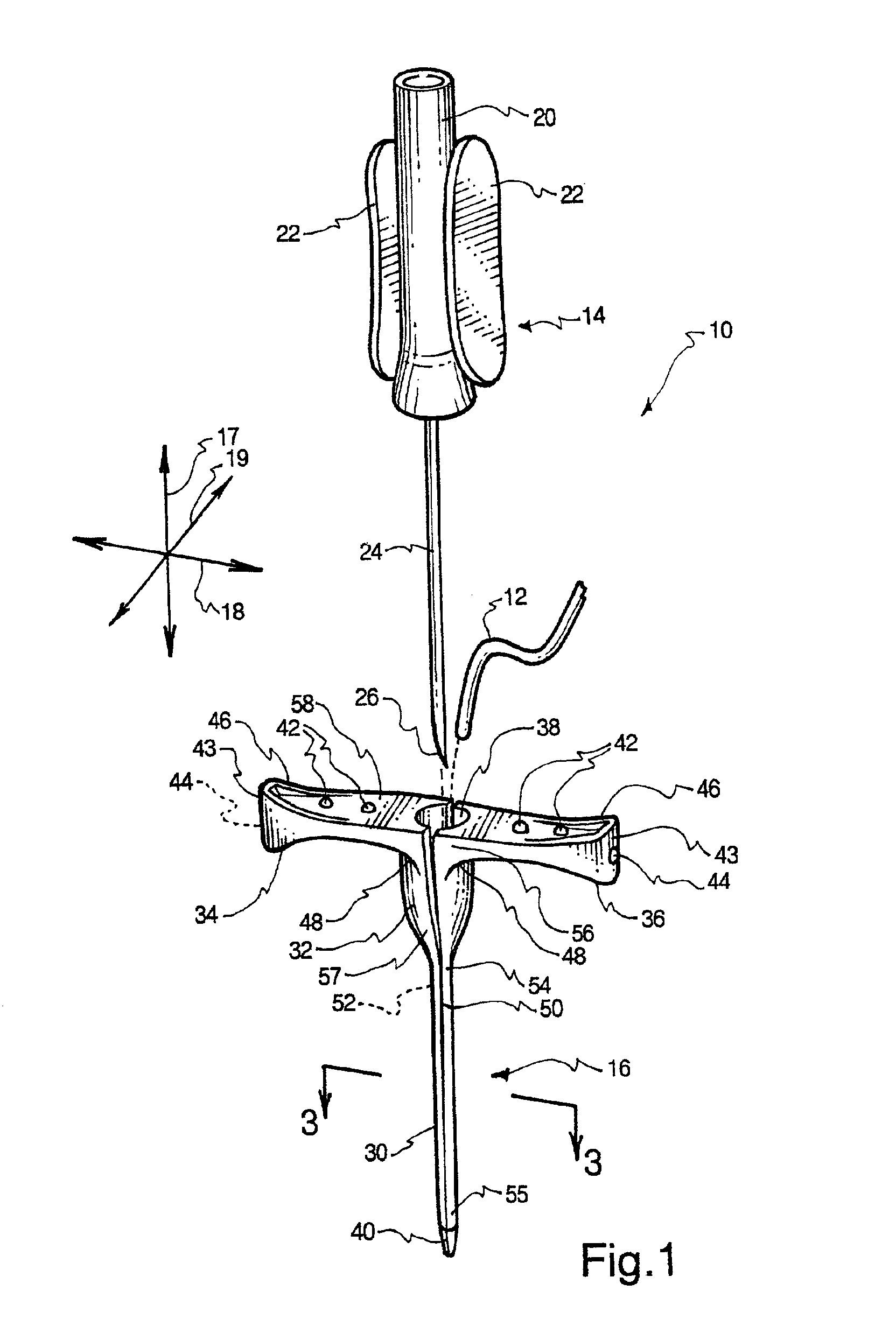
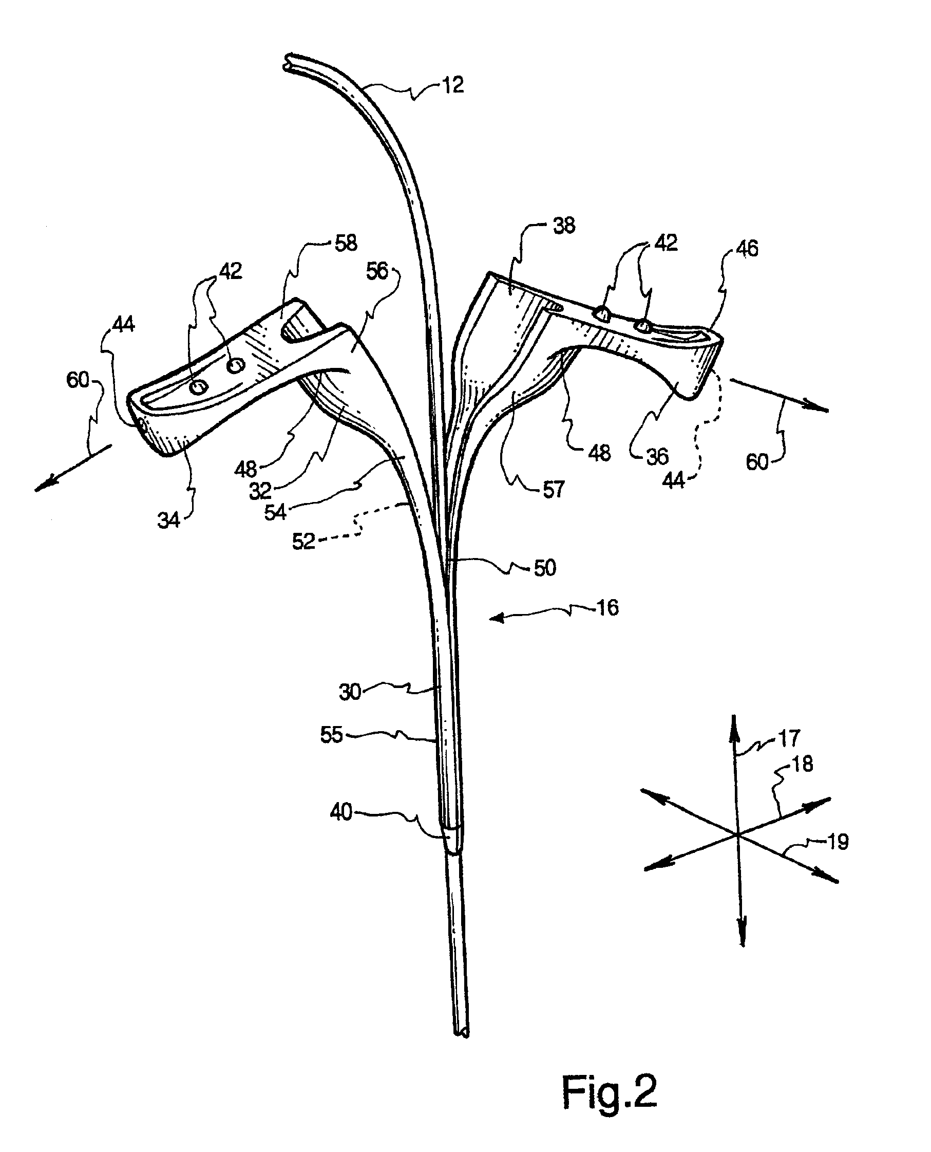
[0013]The sleeve assembly may have a sleeve with a long, tubular shape, a hub with a somewhat wider tubular shape, a first handle extending from the hub, and a second handle extending from the hub, opposite the first handle. A first failure zone and a second failure zone may extend along the length of the sleeve and the hub. The first and second failure zones may be disposed on opposite sides of the sleeve and hub so that the sleeve is divided into two semi-tubular portions. A user can then pull the handles apart to separate the sleeve assembly along the failure zones, into two substantially equal parts. The two halves of the sleeve assembly can then be freely removed from the catheter.
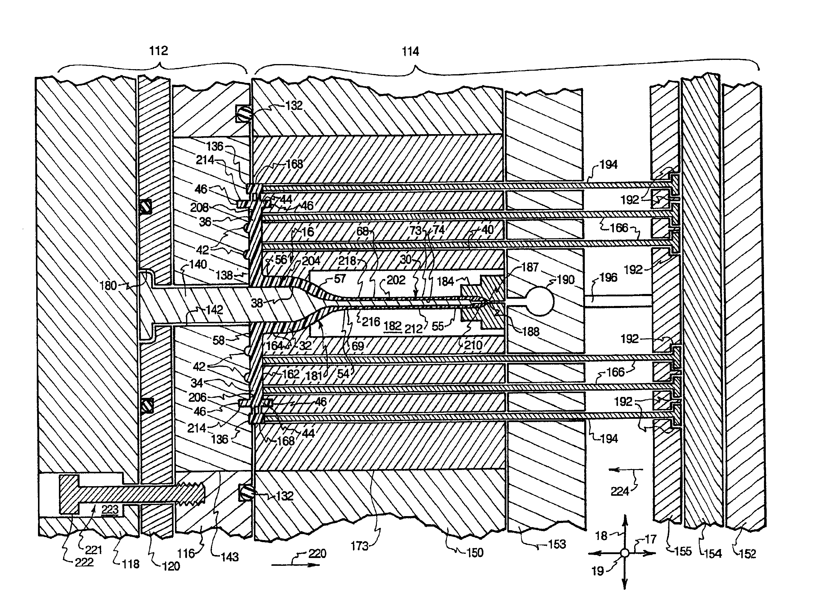
[0016]The present invention also provides a method and related apparatus by which such a sleeve assembly may be inexpensively manufactured through the use of a single injection molding process. In one embodiment, a mold used for the injection molding process has a B-side and an A-side coupled to a nozzle of a plastic injection system. The A-side may have a floating plate and a top clamp plate. The B-side may have a cavity plate, a support plate, a bottom clamp plate, an ejector retainer plate, and an ejector backing plate.
[0019]The cavity plate may have a pair of split inserts that provide the shape of the sleeve portion of the cavity. The split inserts may face each other to form the sleeve portion; one of the ridges may be disposed on each of the split inserts. The cavity plate may also have a pilot bushing into which the core pin seats with a very small amount of clearance, so that air can escape around the pilot bushing while molten plastic is trapped. A vacuum fitting may draw air around the pilot bushing and out of the cavity.
[0023]Additionally, the use of even flows of molten plastic makes it unnecessary to employ extra steps to protect the core pin against bending. Some traditional injection molding processes utilize an external mechanism, such as a hydraulically operated clamp, to tension a core pin or other protrusion to form a bore in the injection molded part. Such mechanisms add to the complexity of the molding apparatus and increase the cycle time of the injection molding process, thereby increasing the cost of the injection molded parts.
[0026]The resulting sleeve assembly may have accurate tip geometry that promotes easier and more comfortable insertion of the catheter introducer into the blood vessel. Furthermore, the sleeve assembly may split reliably and easily, with a minimal likelihood of premature splitting or breakout. The sleeve assembly may be rapidly and inexpensively manufactured by the injection molding process described above, without the need for separate attachment or tipping operations. Consequently, the catheter introducer and method of the present invention may contribute to the comfort, reliability, and cost effectiveness of medical care.

Problems solved by technology

Although the use of the catheter introducer provides some improvements in the catheter insertion process, several problems remain.
Many sleeve assemblies have tips that lack the precision to maintain a close fit over the cannula; hence, they irritate the walls of the blood vessel upon insertion into the vessel with the cannula.
Some sleeve assemblies have a bent sleeve or a non-uniform wall thickness, and are therefore subject to puncture by the cannula or to leakage through a thin-walled portion the sleeve.
Furthermore, many sleeve assemblies cannot be easily removed from the catheter after they are withdrawn from the blood vessel.
Such sleeve assemblies may present an obstruction during operation of the catheter.
Indeed, an attempt to remove a sleeve assembly through the use of scissors or the like can cause damage to the catheter.
Such sleeve assemblies are subject to a number of different problems, including premature splitting (i.e., splitting during assembly with the cannula or during insertion into the blood vessel), breakout (incomplete splitting), leakage through tear seams, and the like.
Additionally, sleeve assemblies are generally somewhat expensive to produce with traditional methods because several manufacturing steps are involved.
The use of such a large number of processes makes the manufacture of sleeve assemblies unduly expensive and time-consuming.

Method used


Image

  • Catheter sleeve assembly and one step injection molding process for making the same
  • Catheter sleeve assembly and one step injection molding process for making the same
  • Catheter sleeve assembly and one step injection molding process for making the same

Examples


Embodiment Construction

[0036]The presently preferred embodiments of the present invention will be best understood by reference to the drawings, wherein like parts are designated by like numerals throughout. It will be readily understood that the components of the present invention, as generally described and illustrated in the figures herein, could be arranged and designed in a wide variety of different configurations. Thus, the following more detailed description of the embodiments of the apparatus, system, and method of the present invention, as represented in FIGS. 1 through 7, is not intended to limit the scope of the invention, as claimed, but is merely representative of presently preferred embodiments of the invention.

[0037]Long, thin, tubular members have traditionally been very difficult to injection mold for a number of reasons. One source of difficulty is the extremely high pressures involved in injection molding processes. Typically, to provide a rapid fill, the plastic is pressurized to severa...


PUM

PropertyMeasurementUnit
Fractionaaaaaaaaaa
Fractionaaaaaaaaaa
Weightaaaaaaaaaa

Abstract

An enhanced catheter introducer and method for making the same are disclosed. The catheter introducer may have a splittable sleeve assembly configured to be inserted into a blood vessel with a cannula. The cannula may then be removed, and a catheter may be inserted into the sleeve assembly. The sleeve assembly may be removed from the catheter by pulling handles of the sleeve assembly in different directions to split the sleeve assembly into two pieces. The sleeve assembly may have failure zones that enable the sleeve assembly to be easily split; the failure zones may take the form of thinned regions running along the length of the sleeve assembly. The sleeve assembly may be injection molded with a single step by injecting flows of molten plastic into a cavity of a mold such that the flows converge into an even distribution about the circumference of the sleeve. The mold may have a core pin designed to fit into the cavity. Through the use of the even distribution of flows, the core pin may seat within the cavity in an untensioned manner.

Description

BACKGROUND OF THE INVENTION[0001]1. Field of the Invention[0002]The present invention relates to medical systems and devices. More specifically, the present invention relates to catheter introducers with plastic sleeve assemblies, and to methods of injection molding sleeve assemblies with a single step.[0003]2. Description of Related Art[0004]There has been a longstanding need in the medical profession for devices and methods by which fluids can be injected into the body or “aspirated,” or removed from the body. Due to the emergence of advanced catheter-related technologies, a larger number of medical procedures that have historically required surgery can now be performed intravenously. Procedures such as angioplasty and exploratory surgery can be carried out without making any incisions other than the puncture necessary to access a blood vessel and insert a catheter. Thus, there is a renewed need for safe, reliable, and comfortable methods of inserting and maintaining a catheter wi...

Claims


Application Information

Patent Timeline
IPC IPC(8): A61M25/06A61M25/00B29C45/00B29C45/40B29C45/26B29C45/36A61M25/08
CPCA61M25/0009A61M25/0668B29C45/0046B29C45/261B29C45/40B29C45/0081A61M25/0606B29C2045/279B29C45/36A61M25/06
Inventor GAWRELUK, CRAIG N.CASTRO, CYNTHIA A.HARDING, WESTON F.JOHNSON, STEVEN W.PARRIS, WAYNE M.GUO, LANTAOLARSEN, MICHAEL C.
Owner BECTON DICKINSON & CO
Learn More