
Method and device for detecting deposit in a conduit

a technology of deposit detection and conduit, which is applied in the direction of testing water, mechanical equipment, instruments, etc., can solve the problems of clogging pipes, affecting production, and expensive techniques, and affecting the quality of the product,

Inactive Publication Date: 2005-05-03
INST FR DU PETROLE +1
View PDF24 Cites 47 Cited by
  • Summary
  • Abstract
  • Description
  • Claims
  • Application Information

AI Technical Summary

Benefits of technology

[0023]control and monitoring means connected to the production source and to the measurement sensor, and adapted to detect when the heat flux corresponding at l

Problems solved by technology

Such techniques, which are often combined, are expensive and are not totally satisfactory, particular because of the difficulties involved in planning them.
Thus, in the event of the operations of scraping and / or adding inhibitor agents being poorly planned, problems arise associated with:production being lost by pipes becoming clogged;safety, with the risk of accidents associated with a hydrate plug appearing, or failure of valves to operate, or with restarting units that have become blocked by high-paraffin crudes gelling; andwith commercial markets being lost by failure to comply with sales contract conditions due to production being stopped.
Such preventative techniques are particularly expensive, given the lack of any real data concerning the quantity of deposit that has already formed inside a pipe, so scraping operations are performed at intervals that are very close together and / or inhibitor additives are added in quantities that are greater than necessary.
Another type of technique that is presently poorly developed relates to seeking to measure the quantity of deposit that has formed inside a pipe.
However, such a technique necessarily disturbs flow, and it need not be capable of performing measurement continuously or of providing a measurement that is reliable.
However it appears that the acoustic impedances of a deposit and of hydrocarbons being transported are substantially identical, so such a technique is not very reliable.

Method used


Image

  • Method and device for detecting deposit in a conduit
  • Method and device for detecting deposit in a conduit
  • Method and device for detecting deposit in a conduit

Examples


Embodiment Construction

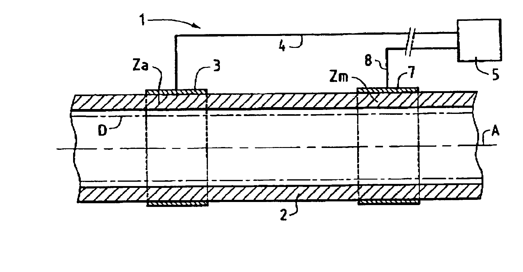
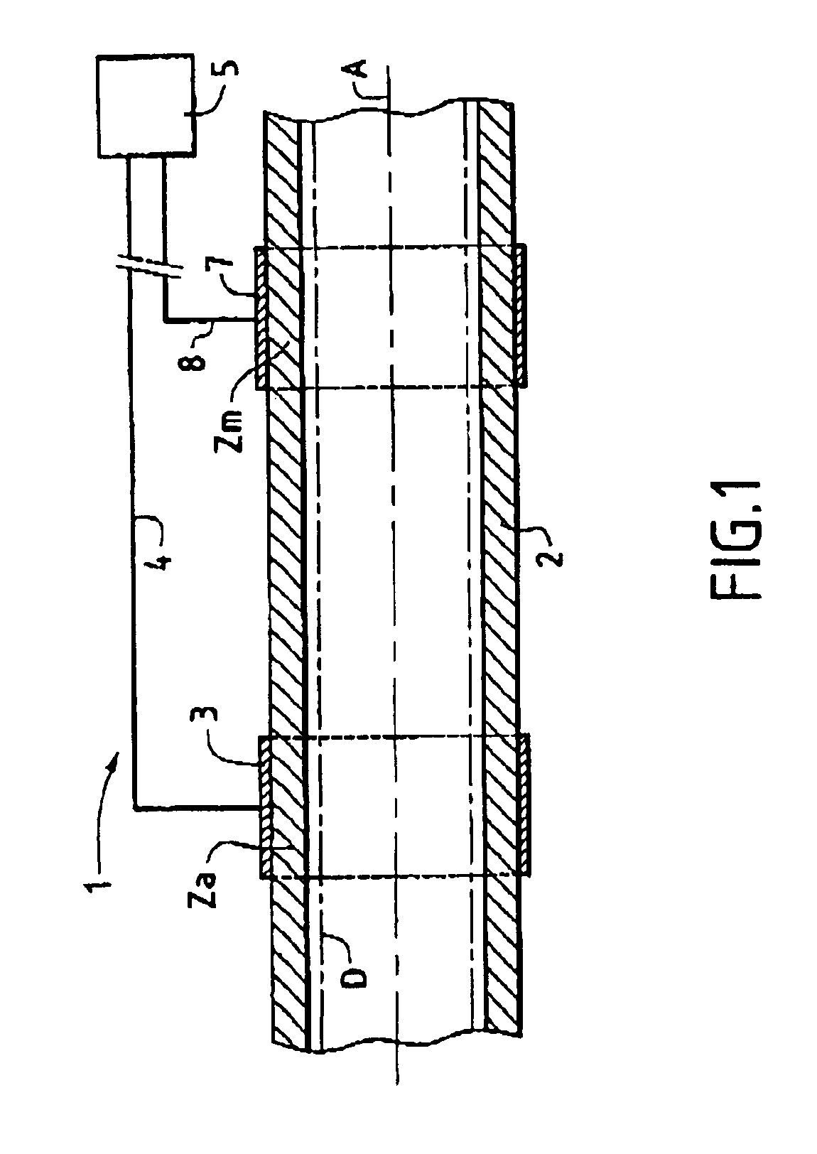
[0028]As can be seen more clearly in FIG. 1, the installation 1 of the invention is adapted to detect a deposit, in the general sense, that might form inside a fluid transport pipe 2, in particular a petroleum transport pipe. In conventional manner, transporting multiphase petroleum fluids runs the risk of forming a deposit or a solid phase such as hydrates, paraffins, asphaltenes, or mineral deposits inside the pipe, as represented diagrammatically by reference D.

[0029]In accordance with the invention, the installation 1 has at least one source 3 for producing a thermal gradient G. Such a production source 3 is for mounting in an “active” zone Za of the outside surface of the pipe 2. It should be considered that the source 3 delivers or extracts a determined quantity of heat over a selected zone of the pipe 2 by any suitable means. By way of example, the quantity of heat delivered to the pipe 2 can be produced by the Joule effect, the Pelletier effect, or the Seebeck effect. In an ...


PUM


Abstract

The invention relates to an installation for implementing a method for detecting a deposit (D) that might form inside a fluid transport pipe (2). According to the invention, the installation comprises:at least one production source (3) for producing a thermal gradient, the source being for mounting on an “active” zone (Za) of the outside surface of the pipe;at least one measurement sensor (7) for measuring heat flux, the sensor being for mounting on a zone (Zm) of the outside surface of the pipe situated relative to the active zone at a given distance in consideration of the length of the pipe; andcontrol and monitoring means (5) connected to the production source (3) and to the measurement sensor (7), and adapted to detect when the heat flux corresponding at least in part to the applied thermal gradient and transmitted by the pipe exceeds a determined threshold indicative of the presence of a deposit inside the pipe.

Description

FIELD OF THE INVENTION[0004]The present invention relates to the field of detecting a deposit or a solid phase liable to form in a pipe for transporting a fluid, in the general sense.[0005]A preferred application of the invention lies in avoiding the risks of clogging in fluid transport pipes, and in particular in pipes for transporting multiphase petroleum fluids.[0006]It is known that such multiphase petroleum fluids can lead to the formation of a solid phase such as hydrates, paraffins, asphaltenes, or other mineral deposits. The solid phase can be deposited at one or more locations in the pipe, thereby reducing flow rate to such an extent as to disturb hydrocarbon transport completely.[0007]Present economic circumstances are encouraging operating companies to significantly reduce investment and operating costs, in particular, by improved control and by seeking to eliminate any risk of such a solid phase being deposited, both in processing installations and in installations for t...

Claims


Application Information

Patent Timeline
IPC IPC(8): F17D3/00F17D3/01G01B21/08
CPCG01B21/085F17D3/01
Inventor ROMANET, THIERRYVOLLE, JEAN-LUCREBER, JEAN DANIEL
Owner INST FR DU PETROLE
Learn More