Method of making a thin-film magnetic head having a magnetoresistive device

a thin-film magnetic head and magnetoresistive technology, applied in the direction of maintaining the head carrier alignment, recording information storage, instruments, etc., can solve the problems of inability to form a desirable pattern, the resistance layer may not be accurately irradiated with the electron beam, and the thin-film magnetic head may fail to function, so as to improve the writing precision of electron beam lithography for forming the second magnetic pole and simplify manufacturing steps

Inactive Publication Date: 2005-05-03
TDK CORPARATION
View PDF9 Cites 17 Cited by
  • Summary
  • Abstract
  • Description
  • Claims
  • Application Information

AI Technical Summary

Benefits of technology

[0040]In this method of making a thin-film magnetic head in accordance with the present invention, the electron beam resist is irradiated with an electron beam after the electrically conductive member comes into contact with the plating electrode used for forming the second magnetic poles. Since the plating electrode electrically connects the forming positions to be formed with the second magnetic poles, electric charges stored near each forming position due to the electron beam irradiation can be led to the outside by way of the electrically conductive member. If the electron beam resist is irradiated with an electron beam after the electrically conductive member comes into contact with the plating electrode while keeping thi

Problems solved by technology

However, the above-mentioned conventional manufacturing technique has problems as follows: For example, when patterning a TMR film, an electron beam resist is applied onto the TMR film and then is irradiated with an electron beam so as to form a resist layer.
At this time, however, the electron beam resist may not be irradiated accurately with the electron beam, whereby the resist layer may not be formed into a desirable p

Method used


Image

  • Method of making a thin-film magnetic head having a magnetoresistive device
  • Method of making a thin-film magnetic head having a magnetoresistive device
  • Method of making a thin-film magnetic head having a magnetoresistive device

Examples


Embodiment Construction

[0071]In the following, preferred embodiments of the present invention will be explained in detail with reference to the accompanying drawings. Here, constituents identical to each other will be referred to with numerals identical to each other, without repeating their overlapping explanations.

[0072]First, before explaining the making methods in accordance with embodiments, outlines of the thin-film magnetic head, head gimbal assembly, and hard disk apparatus obtained by these methods will be explained with reference to FIGS. 1 to 4.

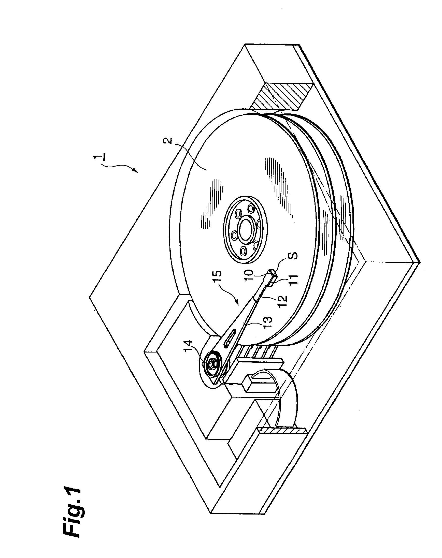
[0073]FIG. 1 is a view showing a hard disk apparatus comprising a thin-film magnetic head obtained by the making method in accordance with an embodiment. This hard disk apparatus 1 is one in which a thin-film magnetic head 10 records / reproduces magnetic information in a recording surface (upper face in FIG. 1) of a hard disk 2 rotating at a high speed by actuating a head gimbal assembly (HGA) 15. The head gimbal assembly 15 comprises a gimbal 12 mounted ...


PUM

PropertyMeasurementUnit
Electrical conductivityaaaaaaaaaa
Magnetoresistanceaaaaaaaaaa

Abstract

In the method of making a thin-film magnetic head in accordance with the present invention, an electron beam resist is irradiated with electron beams in a state where an electrically conductive member is in contact with a magnetoresistive film. Since the magnetoresistive film electrically connects individual forming positions to be formed with magnetoresistive devices, charges stored near the forming positions upon irradiation with the electron beams can be drawn to the outside by way of the electrically conductive member. As a consequence, the electron beams are less likely to lose their rectilinearity, whereby the writing precision for patterning the magnetoresistive film by electron beam lithography can be improved.

Description

BACKGROUND OF THE INVENTION[0001]1. Field of the Invention[0002]The present invention relates to a method of making a thin-film magnetic head using a magnetoresistive device, a method of making a magnetoresistive device assembly, a method of making a head gimbal assembly, and a method of making a hard disk apparatus.[0003]2. Related Background Art[0004]Recently, as hard disk apparatus have been improving their surface recording density, thin-film magnetic heads playing an important role in recording / reproducing magnetic information have also been required to improve their performances. As a thin-film magnetic head, a composite thin-film magnetic head in which a reproducing head having a magnetoresistive device (MR device) and a recording head having an inductive magnetic converting device are stacked on each other has recently become mainstream in place of one carrying out both recording and reproducing by an inductive magnetic converting device. Known as MR devices are AMR (Anisotr...

Claims


Application Information

Patent Timeline
IPC IPC(8): G11B5/39G11B5/31G11B5/60
CPCG11B5/3967G11B5/3977Y10T29/49021Y10T29/49044Y10T29/49046Y10T29/49041Y10T29/49052Y10T29/49048Y10T29/49043
Inventor KASAHARA, NORIAKIKAGOTANI, TSUNEOHATATE, HITOSHI
Owner TDK CORPARATION
Why Eureka
Try Eureka