Eureka AIR delivers breakthrough ideas for toughest innovation challenges, trusted by R&D personnel around the world.

Enhanced flight control systems and methods for a jet powered tri-mode aircraft

Active Publication Date: 2005-04-26
THE BOEING CO
View PDF28 Cites 104 Cited by
  • Summary
  • Abstract
  • Description
  • Claims
  • Application Information

AI Technical Summary

Benefits of technology

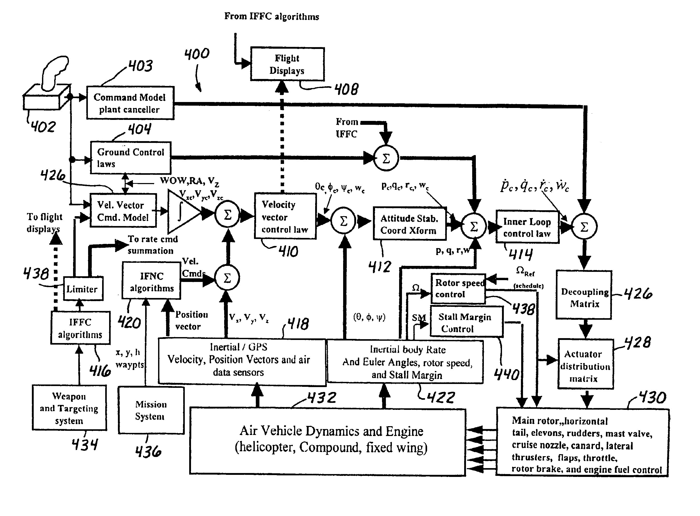
[0014]One advantage of the present invention is that undesirable or excessive flapping of the rotor blade is minimized during the helicopter mode. Another advantage is that speed of the aircraft is controlled without a separate throttle lever, thus simplifying the operations of the aircraft. The present invention provides an intelligent deployment schedule for the mast valve, cruise nozzle, canard, horizontal tail, and rotor blade speed reference that increases the flight envelope during the compound mode. The mast valve and the cruise nozzle can be separately scheduled to provide optimal exit areas for the jet engine, thus preventing the engine stall condition that exists when using the single diverter valve of the '608 patent. The present invention modifies the basic aircraft stabilization and control concept to enhance the aircraft's handling, maneuverability, and safety. The present invention adds several features to the velocity vector control.
[0015]The present invention, together with additional features and advantages thereof, may best be understood by reference to the following description taken in connection with the accompanying illustrative drawings.

Problems solved by technology

One drawback of the '608 patent relates to the diverter valve being unable to adequately exit the engine exhaust during the compound mode causing the engine to experience a choke condition, thus resulting in the engine stalling.
The problem is fatally intolerable for an aircraft.
Another drawback of the '608 patent is the difficulty in determining and maintaining the flight envelope for jet-powered tri-mode aircraft.

Method used


Image

  • Enhanced flight control systems and methods for a jet powered tri-mode aircraft
  • Enhanced flight control systems and methods for a jet powered tri-mode aircraft
  • Enhanced flight control systems and methods for a jet powered tri-mode aircraft

Examples


Embodiment Construction

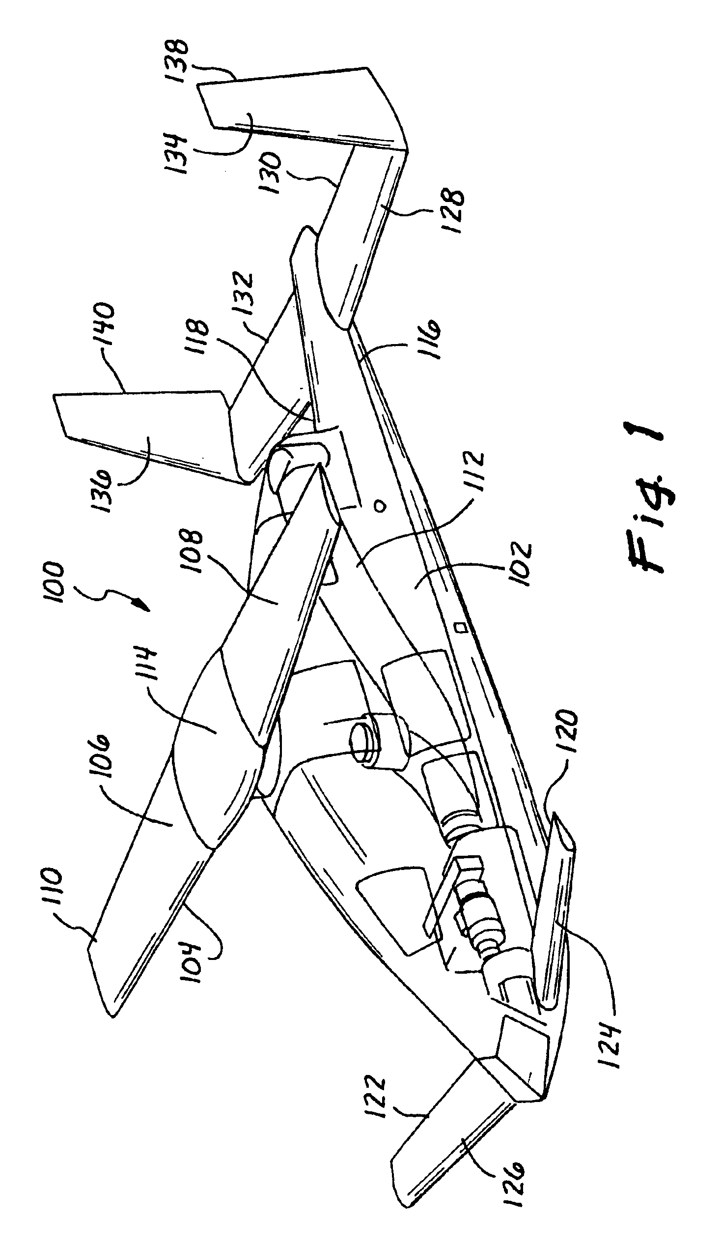
[0035]Referring now more particularly to the drawings, FIG. 1 is a perspective view of a jet-powered tri-mode aircraft 100 according to the present invention. The aircraft 100 provides several advantages, enhancements, and improvements over the '608 patent. From reviewing this disclosure, the advantages, enhancements, and improvements will be apparent to one of ordinary skill in the art.

[0036]The aircraft 100 includes a fuselage 102 and a rotor blade 104 mounted thereon. The rotor blade 104 contains flow ducts 106 and 108, which eliminate the need for an anti-torque system such as a tail rotor or an equivalent structure. Each of the flow ducts 106, 108 serve to transport engine exhaust from the engine to exit nozzles 110, 112 located at the tips of the rotor blade 104. The engine exhaust from the flow ducts 106, 108 spins the rotor blade 104 about the rotor hub 114. The rotor blade 104 preferably comprises symmetrical leading and trailing edges. In the helicopter mode, the front edg...


PUM


Abstract

A method of stabilizing a jet-powered tri-mode aircraft as the aircraft travels in a helicopter mode, a compound mode, and a fixed-wing mode is disclosed. The method includes receiving a plurality of velocity vector component values and velocity vector commands derived from either (1) a number of pilot operated controllers or (2) a commanded array of waypoints, which are used for fully automated flights, and a rotor speed reference value, which is decreased with increasing forward speed to unload the rotor, thereby permitting conditions for stopping the rotor in flight. Stabilization of the commanded velocity vector is achieved in all modes of flight using blended combinations of rotor swashplate controls and aerodynamic controls such as elevons, canards, rudders, and a horizontal tail. Stabilization to the commanded velocity vector includes a plurality of control constraints applied to the pilot stick controllers that prevent penetration of envelope limits.

Description

BACKGROUND OF THE INVENTION[0001]1. Field of the Invention[0002]The present invention relates generally to an aircraft, and more particularly to enhanced flight control systems and methods for a jet powered tri-mode aircraft.[0003]2. Description of the Related Art[0004]U.S. Pat. No. 5,951,608 to Osder, entitled “Flight Control System For Jet Powered Tri-Mode Aircraft,” which is assigned to the assignee of the present invention, discloses a basic flight control system for a jet-powered tri-mode aircraft. The disclosure of the '608 patent is incorporated by reference herein. The jet-powered tri-mode aircraft generally has three primary modes of operation, which are a helicopter mode, a compound mode, and a fixed-wing mode. The jet-powered tri-mode aircraft is designed to take off vertically in helicopter mode and then to fly horizontally in fixed-wing mode.[0005]In the helicopter mode, power is applied to a rotor blade of the aircraft so that the aircraft can take off in a vertical di...

Claims


Application Information

Patent Timeline
IPC IPC(8): B64C27/24B64C27/00B64C39/12B64C27/18B64C39/00G05D1/08
CPCB64C27/18G05D1/0858B64C39/12B64C27/24
Inventor OSDER, STEPHEN S.THOMPSON, THOMAS L.
Owner THE BOEING CO
Why Eureka
Eureka Blog
Learn More