
Sub-flux quantum generator

Inactive Publication Date: 2005-04-26
D-WAVE SYSTEMS
View PDF13 Cites 89 Cited by
  • Summary
  • Abstract
  • Description
  • Claims
  • Application Information

AI Technical Summary

Benefits of technology

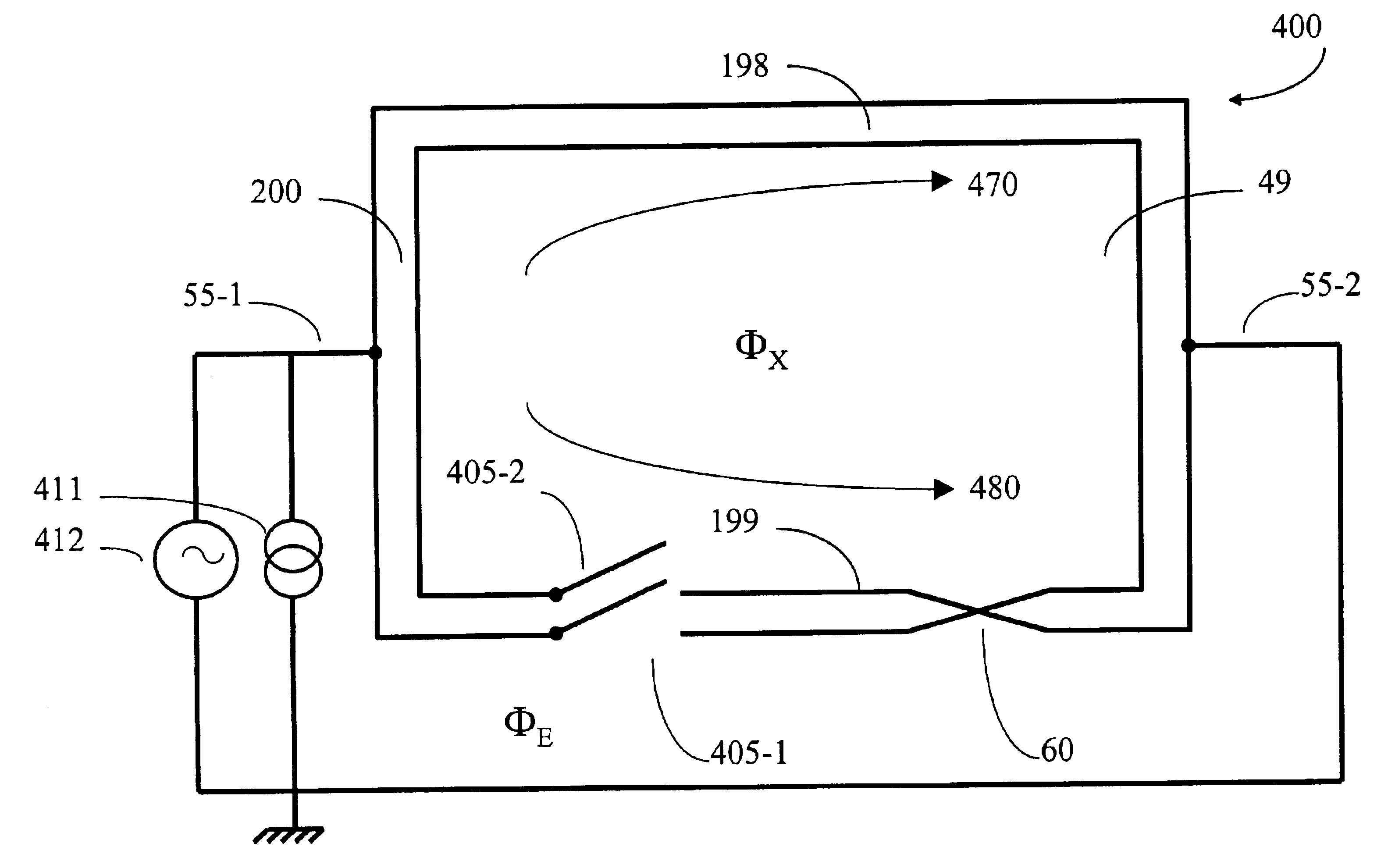
[0017]The present invention provides a switchable stable sub-flux quantum generator. In one embodiment of the invention, an N-turn ring is used to trap fluxon or sub-fluxon amounts of magnetic flux. Furthermore, each turn of the N-turn ring includes a switch. By regulating the switches in the N-turn ring, the amount of magnetic flux in the N-turn ring can be used to control the amount of magnetic flux trapped within the ring with sub-fluxon precision. The switchable N-turn ring provides a reliable external magnetic flux that can be used to bias a persistent current qubit, such as circuit 700, so that the two stable states of the qubit are degenerate.

Problems solved by technology

However, such systems are not particularly well suited for the realization of the desired high number of interacting qubits needed in a quantum computer.
A disadvantage of persistent current qubit 700 is that it is difficult to provide a stable source for the applied magnetic flux fM0 that is necessary to produce the two degenerate states.
Fluctuations in the frustration flux can decohere the states of the qubit making computation difficult or unreliable.
Thus, decoherence results in the loss of the superposition of basis states in a qubit.
Inductance from normal electronics is not suitable for producing degenerate states in a persistent current qubit.
Any disruption in the current through such electronics will disrupt the degenerate states.
Vibrations of the system can cause a change in the level of frustration (level of bias).
Even the briefest interruption in the degeneracy of the states will destroy the quantum computation performed on the qubit.
However, this is not possible in a superconducting ring because the magnetic flux trapped in the center of the ring cannot penetrate the superconducting ring.
However, this is not possible in the ring proposed by Majer et al. because the magnetic flux is induced in the center of the ring by superconducting current in the ring.
While ring 800 represents a significant achievement in the art, it does not provide a satisfactory device for applying an external biasing (frustrating) magnetic field to a persistent current qubit for two reasons.
First, ring 800 does not provide a mechanism for trapping or releasing trapped magnetic flux.
Second, ring 800 is not capable of trapping sub-fluxon quantities of magnetic flux.

Method used


Image

  • Sub-flux quantum generator
  • Sub-flux quantum generator
  • Sub-flux quantum generator

Examples


Embodiment Construction

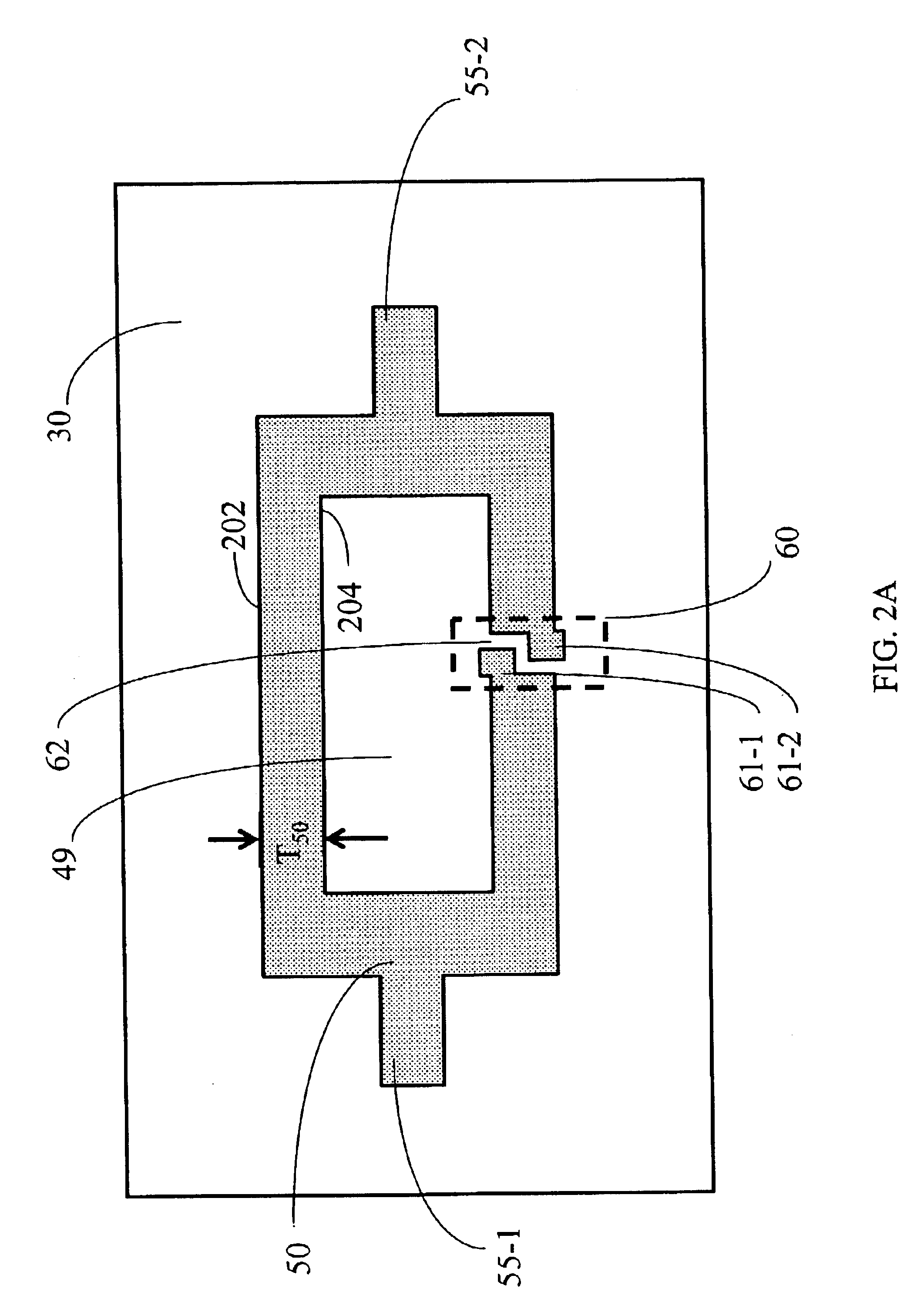
[0033]One embodiment of the present invention provides an N-turn ring that is used to trap fluxon or sub-fluxon amounts of magnetic flux when superconducting current flows through the N-turn ring. As observed experimentally by Henry and Deaver in 1968, the magnetic flux trapped by a superconducting N-turn ring is quantized in multiples of h / N2e, where N is the number of times an inaccessible region is encircled by the N-turn ring, h is Plank's constant, and e is elementary charge. See Henry and Deaver, 1968, Bull. Am. Phys. Soc. 13, 1691; and Olariu and Popescu, 1985, Rev. Mod. Phys. 57:2, pp. 339-436, especially pages 412-413, which are hereby incorporated by reference in their entireties. This relationship assumes that each turn in the N-turn ring encircles approximately the same area. A two-turn superconducting ring can trap one half of a flux quantum (i.e. one half of a fluxon, 0.5×h / 2e). An N-turn ring has N turns. These N turns are optionally intertwined. Furthermore, in one e...


PUM


Abstract

A sub-flux quantum generator includes an N-turn ring having a plurality of connected turns about a common aperture. The width of each respective turn in the N-turn ring exceeds the London penetration depth of a superconducting material used to make the respective turn. The generator includes a switching device configured to introduce a reversible localized break in the superconductivity of at least one turn in the N-turn ring. The generator includes a magnetism device configured to generate a magnetic field within the aperture of the N-turn ring. A method for biasing a superconducting structure that encompasses all or a portion of an N-turn ring. While a supercurrent is flowing through the N-turn ring, a quantized magnetic flux is introduced into the aperture of the N-turn ring using a reversible localized break in a turn in the ring. The quantized magnetic flux is trapped in the ring by removal of the localized break. The trapped flux biases the superconducting structure.

Description

CROSS-REFERENCE TO RELATED APPLICATION[0001]This application claims benefit, under 35 U.S.C. §119(e), of U.S. Provisional Patent Application Ser. No. 60 / 383,579 filed on May 24, 2002 which is incorporated herein, by reference, in its entirety.FIELD OF THE INVENTION[0002]This invention relates to superconducting circuitry. More specifically, this invention relates to devices that generate fractions of a flux quantum.BACKGROUND[0003]Quantum computing is accomplished using the effects of qubits that exhibit quantum mechanical behavior. A qubit is a physical system that is restricted to two or more energy states. A qubit is a quantum bit, the counterpart in quantum computing to the binary digit or bit of classical computing. Just as a bit is the basic unit of information in a classical computer, a qubit is the basic unit of information in a quantum computer. A qubit is conventionally a system having two or more discrete energy states. The energy states of a qubit are generally referred ...

Claims


Application Information

Patent Timeline
IPC IPC(8): G06G7/00H03M1/00G06N99/00H01L27/18H01L39/18H01L39/22
CPCB82Y10/00G06N99/002H01L39/18H01L39/223H01L27/18Y10S977/933G06N10/00H10N69/00H10N60/35H10N60/12
Inventor OMELYANCHOUK, ALEXANDER N.SMIRNOV, ANATOLY Y.
Owner D-WAVE SYSTEMS
Learn More