
Electrical connector having circuit board modules positioned between metal stiffener and a housing

a technology of electrical connectors and circuit board modules, applied in the direction of two-part coupling devices, coupling device connections, printed circuits, etc., can solve the problems of increasing manufacturing costs, increasing the difficulty of assembling connectors, and increasing manufacturing costs, so as to improve metal stiffeners and simplify positioning circuit board modules. , the effect of high density

Inactive Publication Date: 2005-04-26
HON HAI PRECISION IND CO LTD
View PDF104 Cites 154 Cited by
  • Summary
  • Abstract
  • Description
  • Claims
  • Application Information

AI Technical Summary

Benefits of technology

[0012]Accordingly, a first object of the present invention is to provide a high density electrical connector having an improved metal stiffener to simplify positioning circuit board modules.

Problems solved by technology

However, forming a two-piece insulative housing to hold the circuit board modules is complicated, thus increasing the manufacturing cost.
Further, to protect the electrical connector from EMI (Electro Magnetic Interference), an additional EMI shielding member must be provided, which also increases the manufacturing cost.
However, the projections must be accurately aligned with corresponding slots, respectively, thereby increasing the difficulty of assembling the connector.
Further, the arrangement of positioning the shield pieces between the adjacent signal pieces reduces the effective signal density.

Method used


Image

  • Electrical connector having circuit board modules positioned between metal stiffener and a housing
  • Electrical connector having circuit board modules positioned between metal stiffener and a housing
  • Electrical connector having circuit board modules positioned between metal stiffener and a housing

Examples


Embodiment Construction

[0026]Reference will now be made in detail to the preferred embodiment of the present invention.

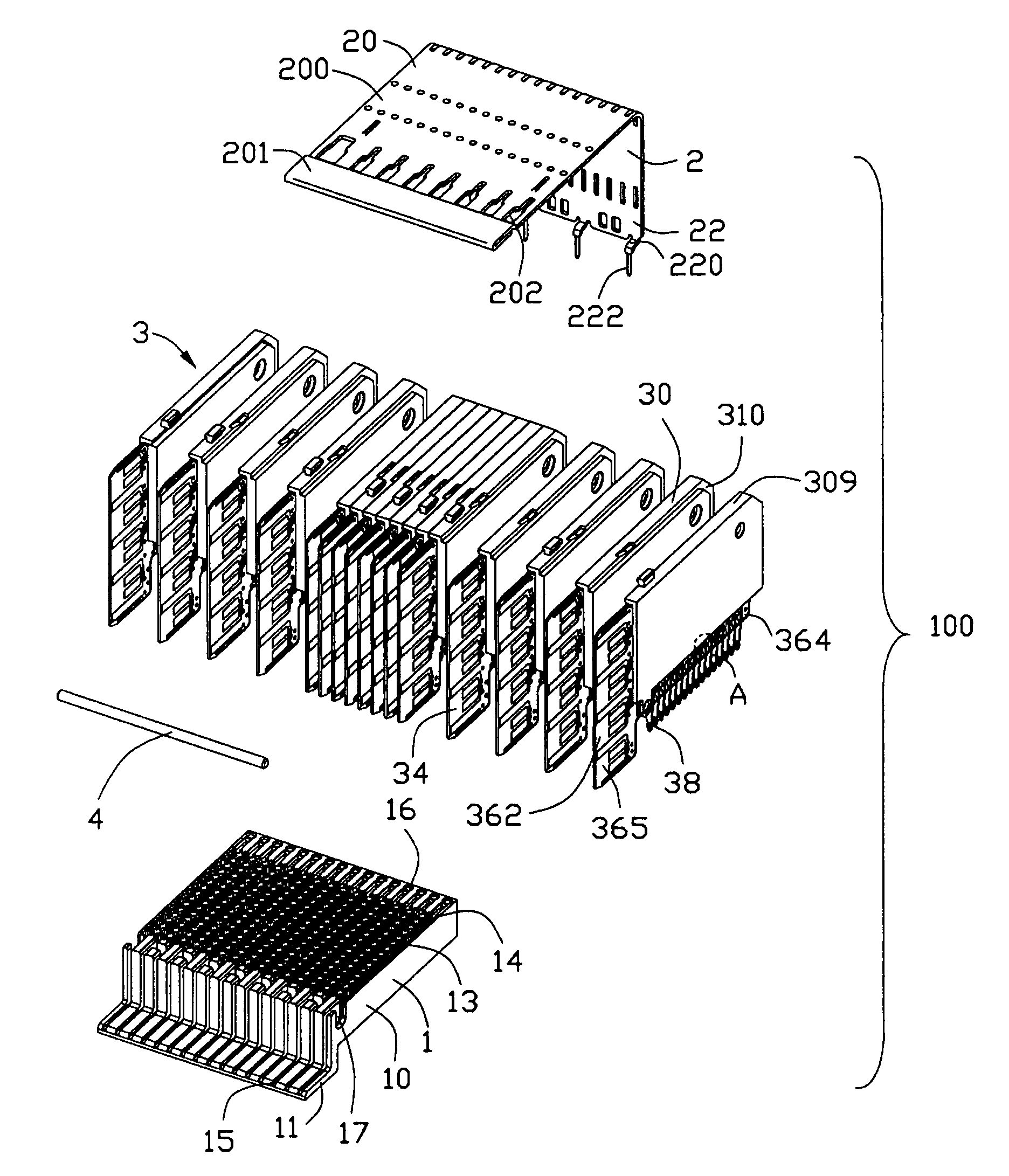
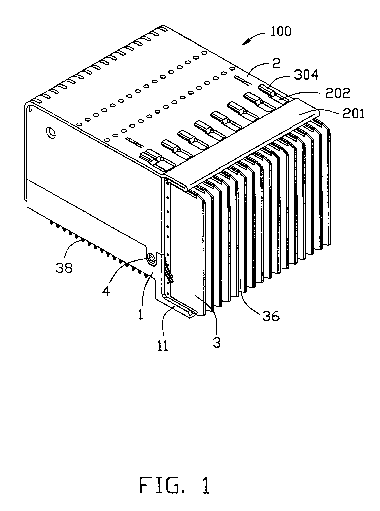
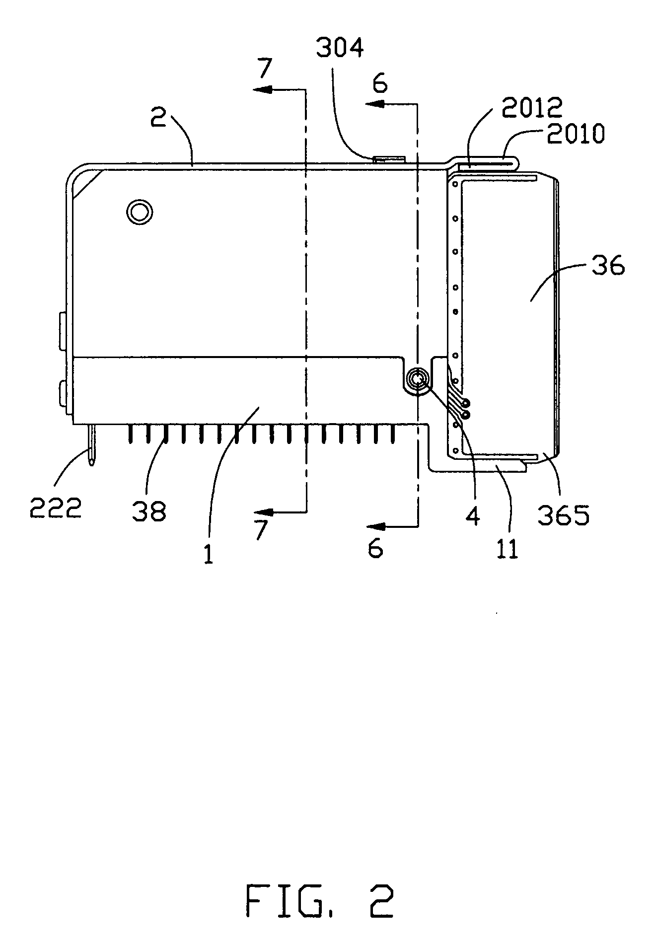
[0027]Referring to FIGS. 1, 2 and 3, an electrical connector 100 in accordance with the present invention comprises a unitary insulating housing 1, a metal stiffener 2, a plurality of individual circuit board modules 3 retained between the housing 1 and the metal stiffener 2, and an alignment pin 4 inserting through the circuit board modules 3.

[0028]The housing 1 includes a rectangular base 10 and a first shroud 11 extending forwardly from a lower portion of a front end of the base 10. The base 10 defines a plurality of parallel slots 13 extending along a longitudinal direction of the housing 1, and plural rows of passageways 14 communicating with corresponding slots 13 and penetrating through a bottom thereof. The first shroud 11 defines a plurality of grooves 15 aligned with corresponding slots 13. The housing 2 defines a row of holes 16 at a rear end thereof and a bore 17 laterally ex...


PUM


Abstract

An electrical connector (100) includes a unitary insulative housing (1) including a base (10) defining a number of parallel slots (13) and a first shroud (11) extending forwardly from the base, a number of parallelly arranged circuit board modules (3) and a metal stiffener (2) attached to the housing. The circuit board modules are retained by and between the metal stiffener and the housing. Each circuit board module includes a dielectric spacer (30), a circuit board (36) attached to the dielectric spacer and received in a corresponding slot of the housing, and a row of press-fit contacts (38) mechanically and electrically connecting with the circuit board. The metal stiffener includes a second shroud (201) vertically spaced from the first shroud. The circuit boards have mating portions (362) disposed between the first and the second shrouds.

Description

CROSS-REFERENCE TO RELATED APPLICATIONS[0001]This patent application is a continuation-in-part (CIP) of U.S. patent application Ser. No. 10 / 651,932 filed on Aug. 29, 2003 and entitled “ELECTRICAL CONNECTOR HAVING ENHANCED ELECTRICAL PERFORMANCE”, and relates to a contemporaneously filed application having the same applicants and the same assignee with the instant application and titled “ELECTRICAL CONNECTOR WITH CIRCUIT BOARD MODULE”.BACKGROUND OF THE INVENTION[0002]1. Field of the Invention[0003]The present invention relates to an electrical connector, and particularly to a high speed electrical connector having plural circuit board modules.[0004]2. Description of Related Art[0005]With the development of communication and computer technology, high density electrical connectors with conductive elements in a matrix arrangement are desired to construct a large number of signal transmitting paths between two electronic devices. Such high density electrical connectors are widely used i...

Claims


Application Information

Patent Timeline
Patent Type & Authority Patents(United States)
IPC IPC(8): H01R12/00H01R12/16H01R13/518H01R13/516H01R13/658H01R13/514
CPCH01R23/688H01R13/518H01R23/7073H01R12/724H01R13/6585
Inventor KORSUNSKY, IOSIF R.YI, CHONG H.HARLAN, TOD M.JUNTWAIT, ERIC D.
Owner HON HAI PRECISION IND CO LTD
Learn More