Eureka AIR delivers breakthrough ideas for toughest innovation challenges, trusted by R&D personnel around the world.

Positive locking push-on precision BNC connector for an oscilloscope probe

a technology of push-on and probe, which is applied in the direction of coupling device connection, coupling parts engagement/disengagement, testing/measuring connector, etc., can solve the problems of affecting the quality of the connection, affecting the accuracy of the probe, so as to achieve the effect of easy engagemen

Inactive Publication Date: 2005-04-26
AGILENT TECH INC
View PDF12 Cites 33 Cited by
  • Summary
  • Abstract
  • Description
  • Claims
  • Application Information

AI Technical Summary

Benefits of technology

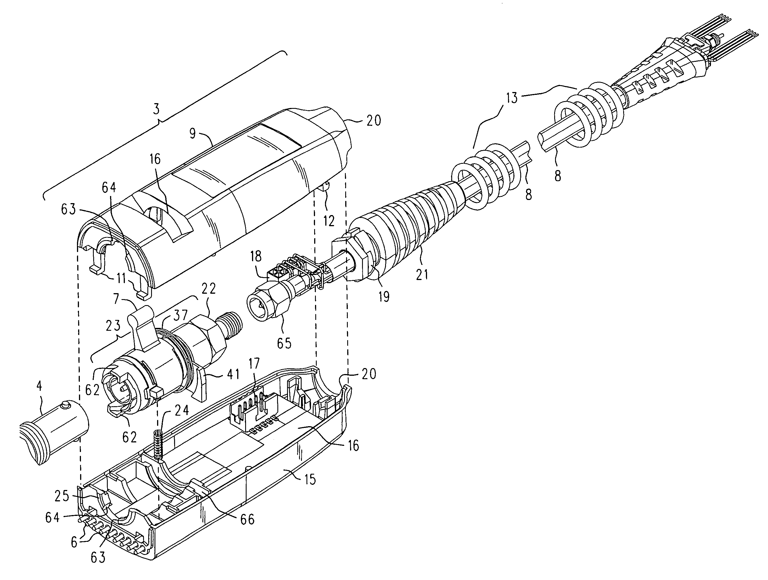
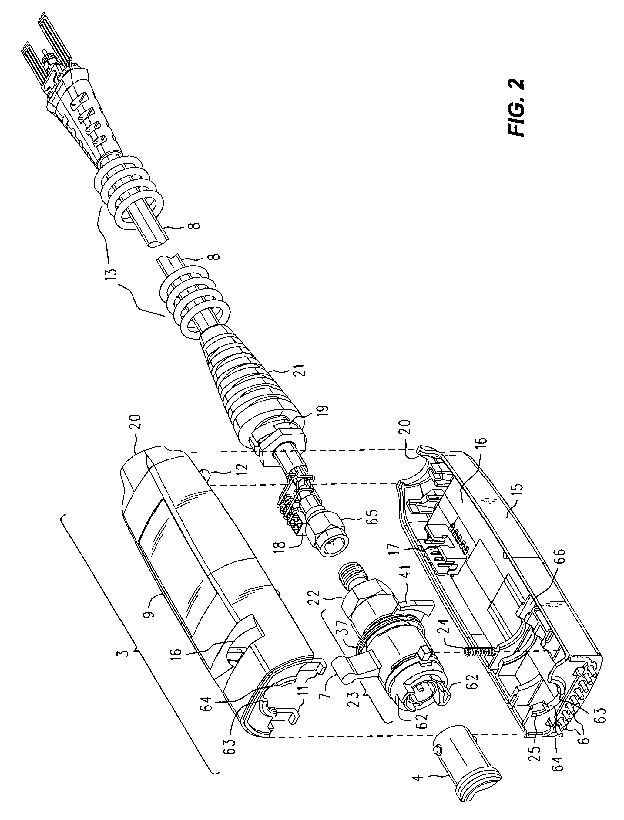
[0023]The second of the three cooperating parts is a self-latching BNC latch having an interior bore by which it snugly yet easily engages, and is then carried upon, the exterior of the male double shell. It rotates easily thereabout. One end of the self-latching BNC latch has ramps and detents for engaging the bayonet pins of a female BNC connector, and the other end has a section of exterior right-hand threads. The section of exterior right-hand threads is proximate the exterior left-hand threads of the male double shell.

Problems solved by technology

The first issue concerns what series connector is used, especially for probes or for direct connections to signals to be measured by the test equipment, and that are not merely an ancillary part of a test set-up.
Despite its popularity, the BNC connector has some significant drawbacks when used as an instrument grade connector for some electronic test equipment, such as top of the line high frequency oscilloscopes.
Finally, since it relies solely on internally supplied spring tension to draw its parts together, it can, when under externally applied tension, allow the mating parts to separate sufficiently to degrade the quality of the connection (greater discontinuity, more loss), sometimes to point where the connection is interrupted altogether (especially if the parts are worn from extended use).
Many of the problems of BNC connectors can be traced to aspects in the design of the male half, which is to say, the part that has the male center conductor pin and that is given the quarter turn twist while gripping a knurled shell we shall call a bayonet latch.
Unfortunately, pulling on the cable, or otherwise inducing external tension urging the two connector halves apart, can overcome the internal spring tension keeping the connectors halves together.
If a sufficient tension is applied the connector halves will draw apart slightly, disturbing the uniform inner diameter of the mated outer shells and possibly introducing an increased ohmic component in the connection.
A similar bad thing happens in connection with the Teflon sleeves.
That fails when the connector halves pull apart, producing another discontinuity owing to a location of altered dielectric constant.
This happens adjacent where the center pins have their “diameter fault,” increasing the resulting discontinuity.
Furthermore, the presence of the Teflon is a bit of a problem in the first place, since it is difficult to machine the stuff to the tolerances needed to reliably perform the magic of the vanishing edges.
Not only is Teflon difficult to machine to tight tolerances, but it won't hold them over time, even if it could be done, since Teflon cold flows so easily.
We are now faced with a situation where the connector of choice is a principal limitation in the overall performance of the scope / probe combination.
It is true that there are other RF connectors that would solve the problem of the rotten RF connection, but they are unsuitable for one or more reasons.
Some are simply too expensive, and, it will be noted, the expensive ones tend to be threaded and / or easily damaged; APC 3.5 connectors come to mind in this regard.
Precision type N connectors would carry the signals all right, but they, too, are threaded, and besides being moderately expensive, they take a lot of panel space.
It was (and still is!) a pretty good connector, and perhaps when in good condition is even comparable to a “precision” type N. But it is as big or bigger than N, is more expensive, and sadly, seems to be on the verge of “going away.” Well, then, so be it.
(We note that it cooperates, with some degradation in performance, with conventional BNC.
The second issue concerns the electrical attachment of scope probes in particular.
Unfortunately, despite its ease of use in attaching and detaching it from the scopes front panel, it is still a conventional BNC connector as far as the quality of the transmission line segment formed by the connector is concerned.
It still has a slitted outer conductor on the male side, and the lack of a separate deliberate mechanism to draw the halves together means that tension produced from supporting the weight of the pod can cause separation of the center conductors and of the outer conductors.
These considerations significantly limit the performance of the scope when higher frequencies are considered.
Because the thumb lever extends through a slot in the pod housing, there is a 90° limitation on the total amount of latch rotation that can be supplied.
With this minimal degree of steepness (essentially to guarantee a sufficient amount of “throw” or axial displacement to move the connector halves together) there is not always enough mechanical advantage to sustain the needed compressive force produced by the “locking” action, particularly when there is a significant sideways force applied to the pod (produced by, say, a tug on the cable).
Furthermore, it is somewhat inelegant in that path through which the compressive force is anchored and applied is more convoluted than direct (the path involves the pod housing, the front panel and the mounting of the connectors themselves).
More elements in the path make the tolerance situation worse, and lessen the amount of rigidity that can expected.

Method used


Image

  • Positive locking push-on precision BNC connector for an oscilloscope probe
  • Positive locking push-on precision BNC connector for an oscilloscope probe
  • Positive locking push-on precision BNC connector for an oscilloscope probe

Examples


Embodiment Construction

[0031]Refer now to FIG. 1, wherein is shown a front perspective view 1 of an electronic instrument 2, such as a digital oscilloscope, having one or more front panel female BNC connectors 4 that receive a positive locking push-on precision male BNC connector assembly 3 (pod housing), say, in support of operation with an active probe (not shown) connected at a distal end of a cable 8. In a manner similar to that explained in the incorporated '841 patent, the positive locking push-on precision BNC connector pod housing is installed by first lining it up and then pushing it toward the scope. That engages the BNC detents, and a simple motion with the thumb against the lever 7 performs a positive locking that fully and forcefully mates the two BNC connector halves. When the pod housing 3 is locked, not only is a precision BNC connection established with connector 4, but a row of spring loaded pins 6 (not visible) on the front of the housing for the push-on assembly 3 engages a row 5 of co...


PUM


Abstract

The push-on latching function of a male BNC latch carried in a housing, and the positive locking of fully mated male and female connectors, are performed by three parts: The first is a male double shell assembly having two male sleeves that receive an intervening BNC female shell. An outer portion near the middle of the male double shell carries several turns of an exterior left-hand thread. The second is a spring biased self-latching BNC latch having an interior bore by which it snugly engages, and then rotates upon, the exterior of the male double shell. One end of the BNC latch has ramps and detents for engaging the bayonet pins of a female BNC connector, and the other end has a section of exterior right-hand threads proximate the exterior left-hand threads of the male double shell. The third is a barrel that has a bore therethrough with both left and right hand internal threads that engage the exterior threads of the BNC latch and the male double shell. Rotation of the barrel in one direction causes the BNC latch to move toward the male double shell, and pulls the male assembly toward the female connector for full and locked mating.

Description

REFERENCE TO RELATED APPLICATIONS[0001]The subject matter of this disclosure is related to that which is disclosed in U.S. Pat. No. 6,095,841 entitled PUSH-LOCK BNC CONNECTOR, filed 20 Mar. 1998 by Jimmie D. Felps, was issued 1 Aug. 2000, and assigned to Agilent Technologies of Palo Alto, Calif. Because of the similarity in subject matter, and for the sake of brevity in the present case, U.S. Pat. No. 6,095,841 is hereby expressly incorporated herein by reference, and will be referred to either as “PUSH-LOCK BNC CONNECTOR” or as “the incorporated '841 patent” or perhaps merely as “. '841” where the context excludes any ambiguity.[0002]The subject matter of this disclosure is also related to, and makes use of, that which is disclosed in U.S. patent application Ser. No. 10 / 284,226 entitled PUSH-LOCK PRECISION BNC CONNECTOR, filed 29 Oct. 2002 by Jimmie D. Felps and assigned to Agilent Technologies of Palo Alto, Calif. Because of the similarity in subject matter, and for the sake of br...

Claims


Application Information

Patent Timeline
IPC IPC(8): H01R11/18H01R13/629H01R11/11
CPCH01R11/18H01R13/62933H01R13/62905H01R2201/20
Inventor CANNON, JAMES E.
Owner AGILENT TECH INC
Why Eureka
Eureka Blog
Learn More