
High security combination padlock with locking bar

a combination padlock and locking bar technology, applied in padlocks, building locks, constructions, etc., can solve the problems of unauthorized individuals, unauthorized individuals are incapable of gaining access to the terminating, locking end of the locking bar, etc., to prevent external contaminants from reaching the rotating components. , to achieve the effect of sealing the rotating components

Inactive Publication Date: 2005-04-26
SUN LOCK COMPANY LIMITED -THE-
View PDF1 Cites 31 Cited by
  • Summary
  • Abstract
  • Description
  • Claims
  • Application Information

AI Technical Summary

Benefits of technology

[0014]By employing the present invention, all of the difficulties and drawbacks of the prior art constructions are fully eliminated and an effective, easily produced, high security padlock is achieved which employs a combination system for fully operating the padlock. Furthermore, the high security, combination padlock of the present invention virtually eliminates the ability of unauthorized persons from opening the padlock using known picking techniques. In addition, the padlock construction of the present invention is designed with the interior chambers thereof virtually sealed from ambient surroundings, thereby preventing unwanted contamination from entering the interior of the lock and / or the rotating components thereof. In this way, the prior art degradation and interference of the lock operation by contamination is virtually eliminated.
[0015]In accordance with the present invention, a minimum number of components are employed in combination with a housing and an elongated movable locking bar or shackle in order to provide the desired, unique combination lock construction of this invention. By employing a minimum number of components in the construction of the high security, combination padlock of this invention, a highly efficient and cost effective product is realized.
[0018]Another feature incorporated into the combination padlock of the present invention is a unique tumbler or clutch wheel construction which cooperates with the rotating dials to virtually eliminate any possibility that an unauthorized person would be capable of gaining access to the padlock by known combination lock picking techniques. In this unique construction, each tumbler or clutch wheel is constructed with a plurality of radially extending fins formed thereon, with each of the fins being arcuately spaced from the adjacent fin in a non-symmetrical pattern. This non-symmetrical spacing is most easily achieved by having each of the fins arcuately spaced from each adjacent fin by unequal radial distances.
[0023]In addition, a set-screw member is threadedly engaged with the housing or body of the padlock positioned between the normal, operating position of the radial post and the key-hole slot. As a result, axial movement of the slider shaft during normal operation causes the post to contact the set screw when aligned therewith, thereby preventing accidental entry into the combination setting / resetting mode.
[0024]Whenever the user wishes to set or re-set the combination, the set screw must be partially withdrawn from the housing or body in order to enable the radial post to pass the set screw and enter the keyhole slot. In this way, accidental movement of the slider shaft into the set / re-set mode is eliminated and users are assured that only intentionally entered combinations will open the padlock.

Problems solved by technology

One of the problems that has existed with prior art structures is the ability of unauthorized individuals, seeking to break open a prior art padlock, to be able to forcibly move the locking bar of these prior art padlocks by impacting upon a terminating end of the locking bar.
As a result, any unauthorized individual is incapable of gaining access to the terminating, locking end of the locking bar since the terminating, locking end of the locking bar is securely retained within an integrally formed portion of the housing or body.

Method used


Image

  • High security combination padlock with locking bar
  • High security combination padlock with locking bar
  • High security combination padlock with locking bar

Examples


Embodiment Construction

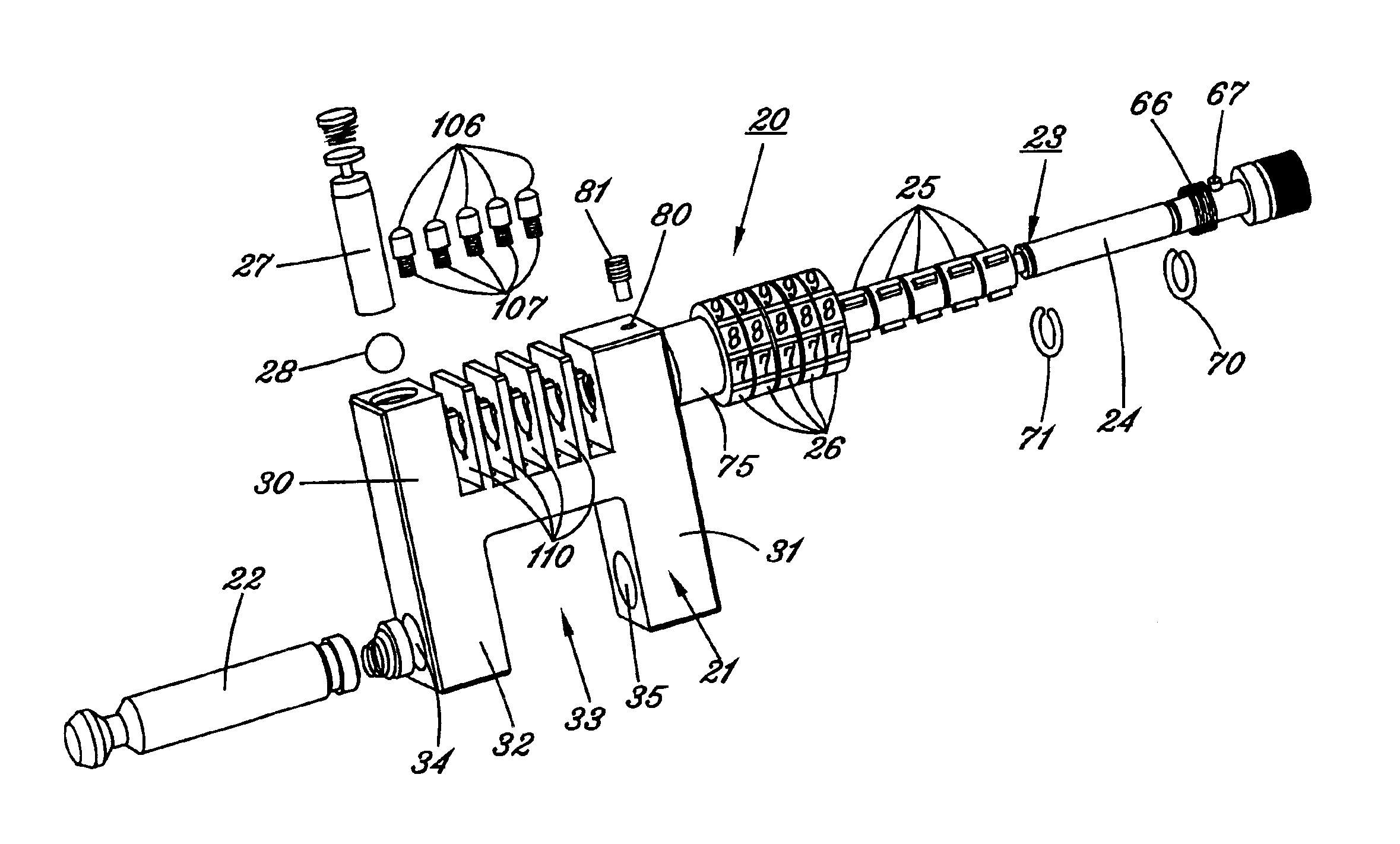
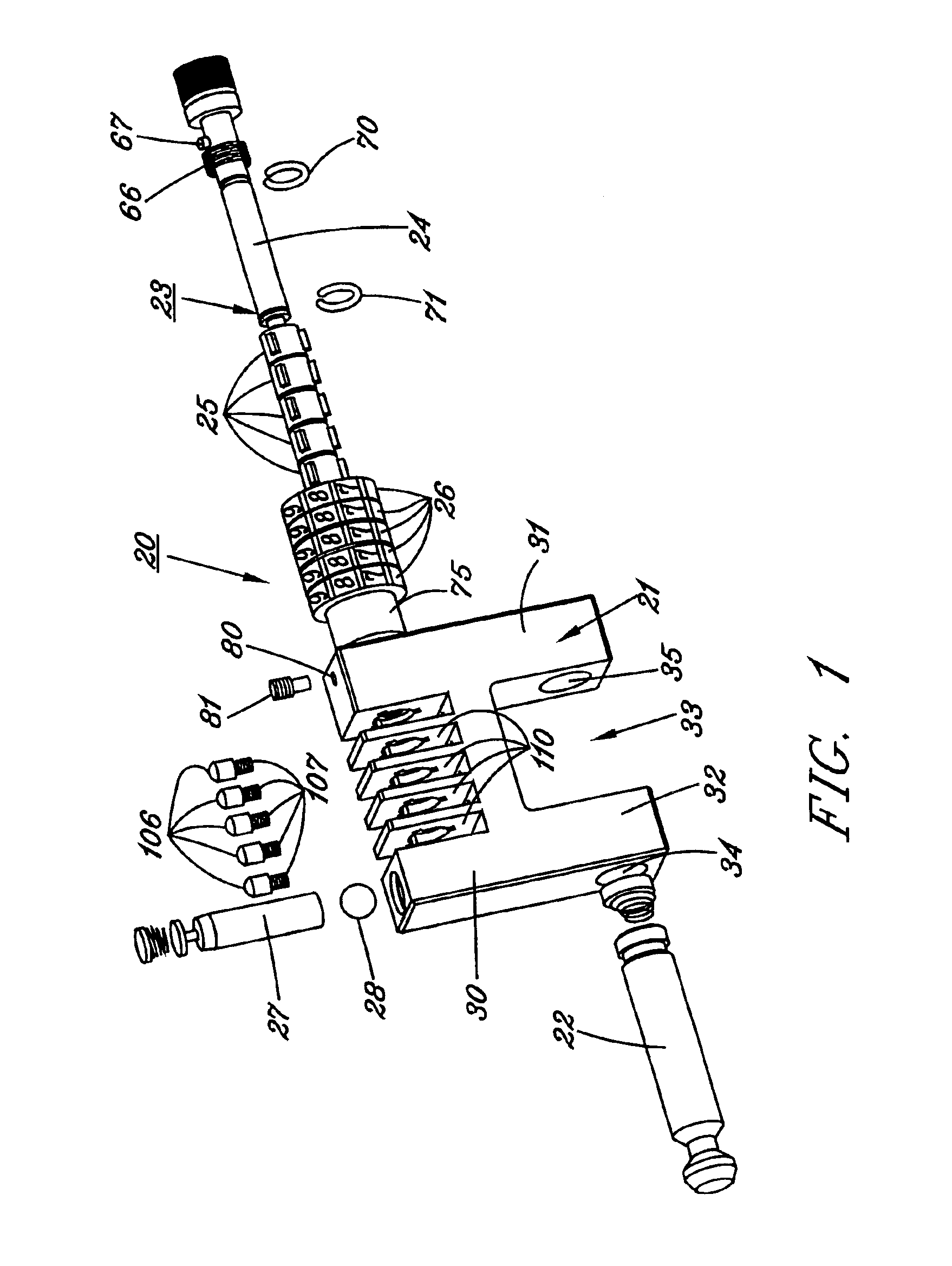
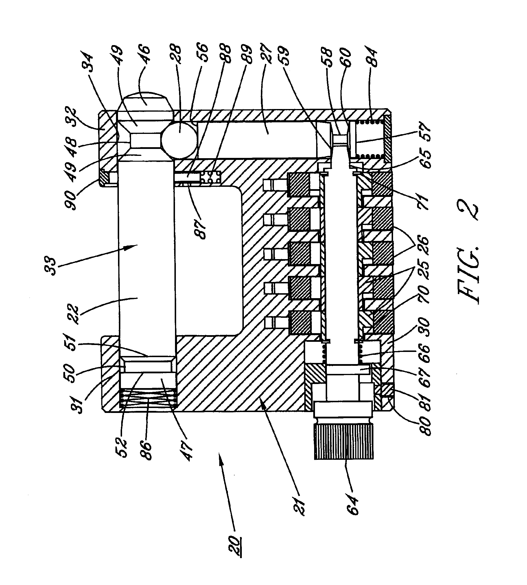
[0041]By referring to FIGS. 1-14, along with the following detailed disclosure, the construction and operation of high security combination padlock 20 of the present invention can best be understood. In the drawings and the following detailed disclosure, alternate preferred embodiments of the present invention are fully disclosed. However, the present invention can be implemented using further alternate constructions, which alternate constructions are intended to be within the scope of the present invention. Consequently, the embodiments disclosed herein and shown in the drawings are provided for exemplary purposes only and is not intended as a limitation of the present invention.

[0042]In FIGS. 1-10, one embodiment of high security, combination padlock 20 of the present invention is fully depicted using a minimum number of principal components, thereby substantially reducing the complexity found in most prior art combination locks. In addition, this embodiment of the present inventi...


PUM


Abstract

By forming a combination padlock from heavy duty metal throughout with an enlarged, heavy duty locking bar or shackle being employed having a tamper-proof holding cavity for the terminating, locking end of the locking bar, an effective, easily produced, high security padlock is achieved which employs a combination system for fully operating the padlock. In addition, the combination padlock of the present invention incorporates tumbler or clutch wheel constructions which cooperate with the rotating dials to virtually eliminate any possibility that an unauthorized person would be capable of gaining access to the padlock by known combination lock picking techniques by forming each tumbler or clutch wheel with a plurality of radially extending fins formed thereon, with each of the fins being arcuately spaced from the adjacent fin in a non-symmetrical pattern. Furthermore, the padlock of the present invention incorporates a unique combination setting and re-setting assembly which employs a slider shaft incorporating a radially extending post, which must pass through a key-hold slot formed in the body or housing of the padlock for activating the combination setting or re-setting mode, and cooperates with a set screw member threadedly engaged with the housing or body of the padlock which controls the axial movement of the shaft.

Description

RELATED APPLICATIONS[0001]This application is a Divisional of Ser. No. 10 / 076,775, filed Feb. 13, 2002 now U.S. Pat. No. 6,675,614 entitled High Security Combination Padlock with Locking Bar.TECHNICAL FIELD[0002]This invention relates to padlocks and, more particularly, to combination padlocks constructed for use in high security and high resistance applications.BACKGROUND ART[0003]Numerous lock constructions have been developed and are widely employed by individuals to prevent unauthorized persons from gaining access to any area which has been closed and locked. Although many locks are constructed to be opened by a key, numerous combination locks have been developed which are opened by knowledge of a particular combination.[0004]One particular type of combination lock that has become very popular, due to it ease and convenience of use, is a combination lock which employs a plurality of rotatable independent dials, each of which comprises a plurality of indicia, usually numbers or l...

Claims


Application Information

Patent Timeline
IPC IPC(8): E05B37/02E05B37/00E05B17/00E05B67/36E05B67/00E05B37/06E05B67/22
CPCE05B37/025E05B17/0062E05B67/365Y10T70/43Y10T70/417Y10T70/424Y10T70/7305Y10T70/441Y10T70/7322
Inventor LAI, ERIC
Owner SUN LOCK COMPANY LIMITED -THE-
Learn More