
Compressor with unloader valve between economizer line and evaporator inlet

a compressor and unloader technology, which is applied in the direction of machines/engines, liquid fuel engines, lighting and heating apparatus, etc., can solve the problems of compressor damage, large refrigerant mass flow through the evaporator, etc., and achieve the effect of simplifying the compressor replacemen

Inactive Publication Date: 2005-04-26
CARRIER CORP
View PDF6 Cites 47 Cited by
  • Summary
  • Abstract
  • Description
  • Claims
  • Application Information

AI Technical Summary

Benefits of technology

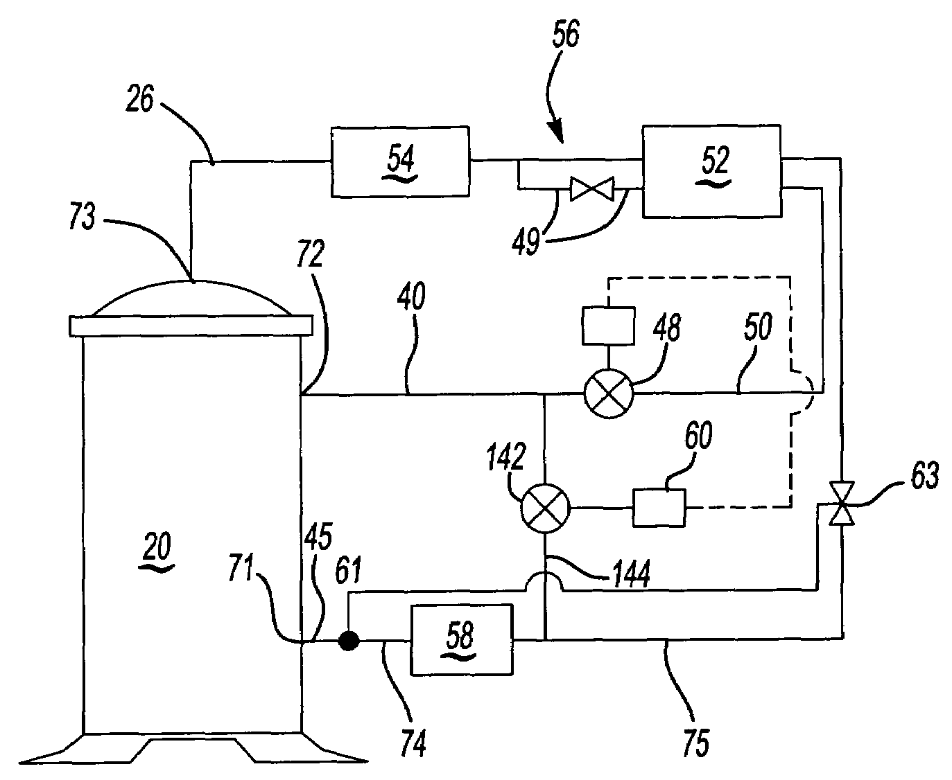
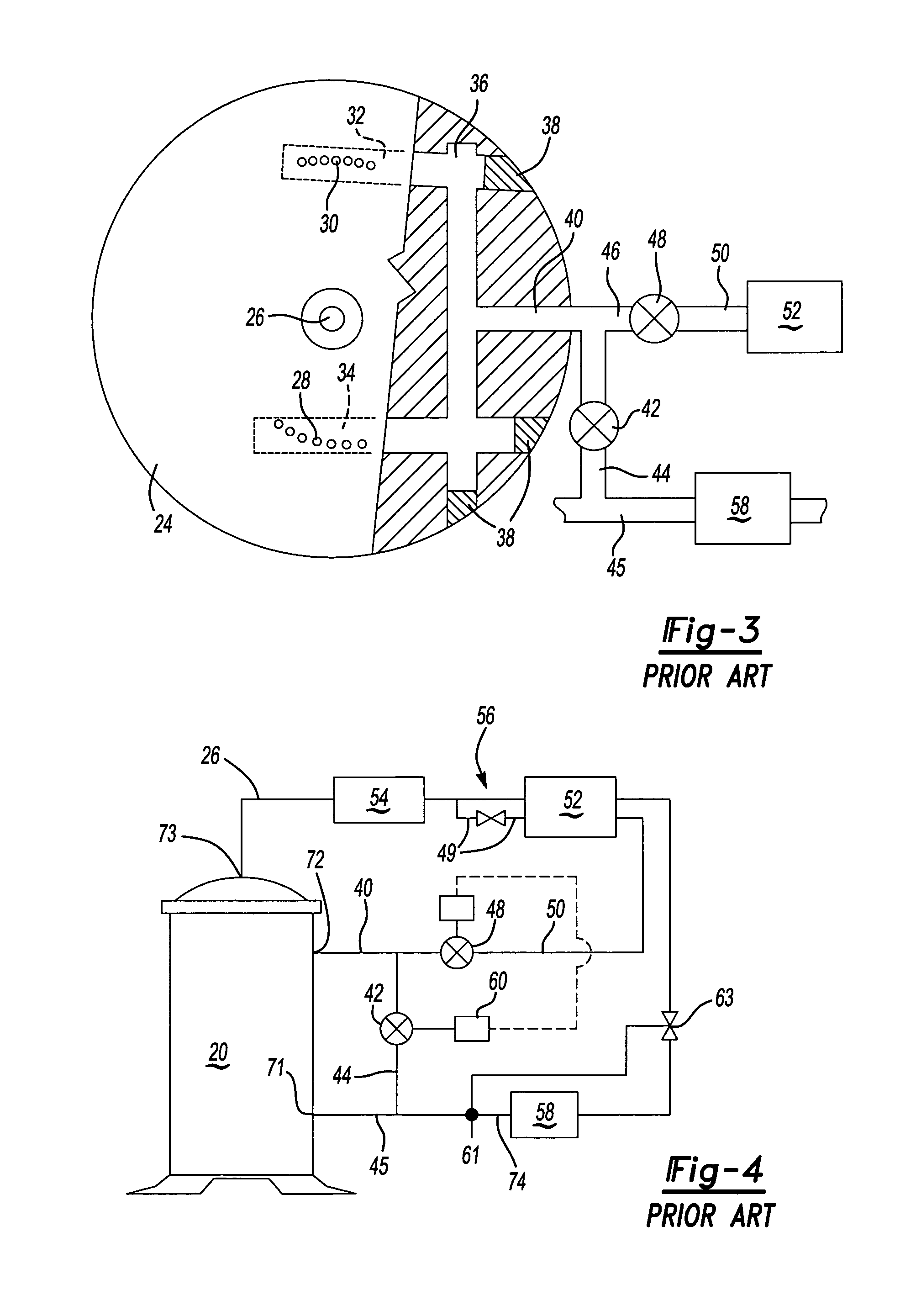
[0008]The present invention provides several benefits over the prior art that returns refrigerant from an intermediate compression point directly to the suction line. In this invention, the refrigerant from the intermediate compression point is returned upstream of the evaporator (preferably at the location between the main expansion valve and the evaporator entrance) instead of being returned downstream of the evaporator (at a location between the evaporator exit and compressor suction port). This results in a greater refrigerant mass flow through the evaporator during unloaded operation over the prior art. Increased refrigerant mass flow improves return flow of oil to the compressor during unloaded operation, increasing the efficiency of the evaporator. Improved oil return also minimizes a risk of pumping the oil out of the compressor shell and storing it in the evaporator. If the oil is pumped out from the compressor, then the compressor could be damaged because bearings and the pump set may not receive adequate lubrication.
[0010]In another feature, the prior art had an unloader bypass valve just outside the compressor. As such, the valve and associated piping, etc. was often in the way should it become necessary to replace the compressor. By moving the bypass line and the unloader bypass valve away from the compressor, more space surrounding the compressor is created, which simplifies the compressor replacement.

Problems solved by technology

This results in a greater refrigerant mass flow through the evaporator during unloaded operation over the prior art.
If the oil is pumped out from the compressor, then the compressor could be damaged because bearings and the pump set may not receive adequate lubrication.

Method used


Image

  • Compressor with unloader valve between economizer line and evaporator inlet
  • Compressor with unloader valve between economizer line and evaporator inlet
  • Compressor with unloader valve between economizer line and evaporator inlet

Examples


Embodiment Construction

[0018]As an example of a compressor type suitable for this invention, a prior art scroll compressor pump set 19 is illustrated in FIG. 1 having an orbiting scroll element 22 which includes an orbiting scroll wrap 23 and a fixed, or non-orbiting, scroll element 24 which includes a non-orbiting scroll wrap 25. The scroll wraps interfit and surround discharge port 26. As known, the orbiting scroll element 22 orbits relative to the non-orbiting scroll element 24 and the scroll wraps 23 and 25 selectively trap pockets of refrigerant which are compressed towards discharge port 26. A plurality of ports 28 and 30 are formed in the base 31 of the non-orbiting scroll element 24. Alternately, ports 28 and 30 may consist of a pair of single, larger ports. The ports may also extend through the wraps 23, 25 or be in other locations. In the position shown in FIG. 1, ports 28 and 30 are just being uncovered by the orbiting scroll wrap 23 at about the same time as compression chambers 27 and 29 are ...


PUM


Abstract

A compressor has an economizer injection line communicating into the compressor compression chambers. An unloader valve selectively communicates the economizer injection line back to a point upstream of the evaporator. When the compressor is run in unloaded mode, partially compressed refrigerant is thus returned to a point upstream of the evaporator. In unloaded mode, this results in a higher refrigerant mass flow through the evaporator, as compared to prior art where the bypassed refrigerant was returned downstream of the evaporator. This increases system efficiency by more effectively returning oil which otherwise might be left in the evaporator back to the compressor. Also, the amount of refrigerant superheat entering the compressor in unloaded operation is reduced as compared to the prior art compressor systems, wherein the bypassed refrigerant is returned directly to the compressor suction line. Reduced refrigerant superheat increases system efficiency, improves motor performance and reduces compressor discharge temperature.

Description

BACKGROUND OF THE INVENTION[0001]This invention relates to a unique placement for an unloader valve that is particularly beneficial to a compressor that operates in economized cycle and can also be unloaded through an intermediate economizer port.[0002]One of the compressor types that are especially suited for this invention is a scroll compressor. Scroll compressors are becoming widely utilized in compression applications. However, scroll compressors present several design challenges. One particular design challenge is achieving reduced capacity levels when full capacity operation is not desired.[0003]Thus, scroll compressors, as an example, have been provided with unloader bypass valves that divert a portion of the compressed refrigerant back to a compressor suction port. In this way, the mass of refrigerant being compressed is reduced. Of course, other compressor types may also have a bypass valve for similar purpose.[0004]On the other hand, in many refrigerant compression applic...

Claims


Application Information

Patent Timeline
IPC IPC(8): F04C29/04F25B1/04F25B49/02F04C28/24F04C29/12
CPCF04C28/24F04C29/042F04C29/122F25B1/04F25B49/022F25B2700/21151F25B2400/13F25B2600/0261F25B2600/2509F25B2600/2513
Inventor LIFSON, ALEXANDER
Owner CARRIER CORP
Learn More