
System and method for reducing resistance to flow in liquid reservoir extraction

a liquid reservoir and flow resistance technology, applied in the direction of drilling casings, drilling pipes, borehole/well accessories, etc., can solve the problems of not being able to extract the most of the oil from the ground, the oil reservoir begins to lose pressure, and the oil is actually a lot of oil left in the reservoir, so as to increase the oil flow into the well and reduce the oil flow

Inactive Publication Date: 2008-06-05
GEOSCI INNOVATIONS
View PDF6 Cites 3 Cited by
  • Summary
  • Abstract
  • Description
  • Claims
  • Application Information

AI Technical Summary

Benefits of technology

[0020]Generally, the invention involves various systems and methods that can be used to resonate and / tune the pressure in a forcible volume created within a well having its own natural resonance or harmonic properties. The pressure resonance according to the present invention causes the amplitude of the pressure response of the oil and / or groundwater layers that form in the well during the oil extraction process to be maximized, increasing the output of the well. In one embodiment, the pressure resonance introduced into the well is tuned according to accommodate for the changes in the natural resonance of the well as oil is being extracted. Such tuning would involve adjusting the timing and / or duration of the high and low pressure levels or positive and negative pressure levels of the resonant pressure to maximize well output. Such, timing and / or duration adjustments are repeated until the introduced pressure resonance phase lock with the natural resonance of the well. As herein defined, a liquid filled column refers to any layer of oil and / or groundwater within the well that is subject to extraction.
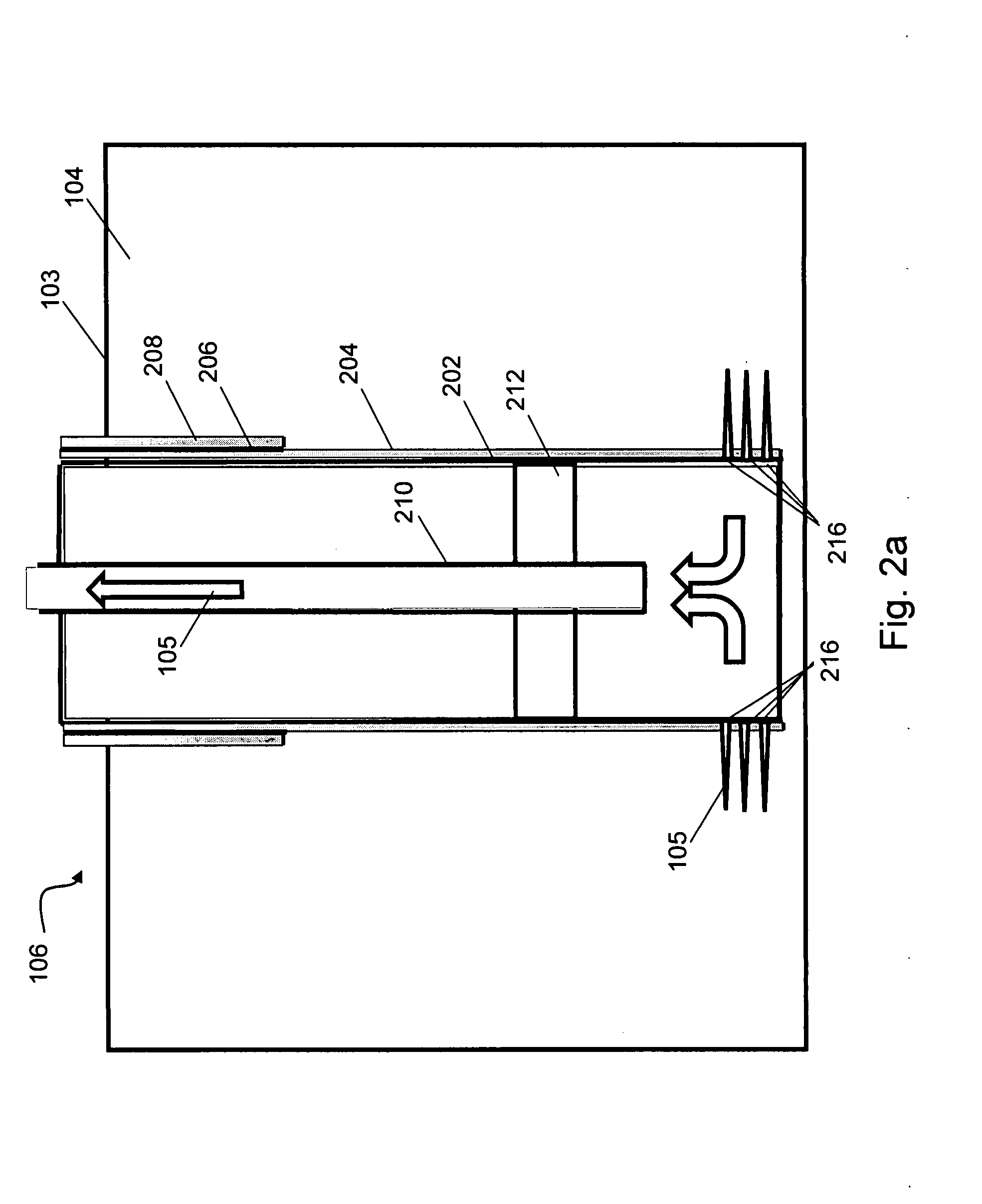
[0026]In accordance with the invention, a positive pressure, which is a pressure greater than ambient pressure, is introduced into the forcible volume to cause the near well formation to expand thereby increasing oil flow into the well. The pressure in the forcible volume is then lowered to a negative pressure, which is a pressure less than ambient pressure, to cause the near well formation to contract thereby decreasing oil flow into the well. The pressure in the forcible volume is repeatedly increased to a positive pressure and then decreased to a negative pressure in a cyclic manner so as to cause the pressure pressure response of the liquid filled column to increase, increasing the output of the well. This pressure resonation process is controlled by a control system to maintain an appropriate resonant drive based on measuring the amplitude and phase of the pressure pressure response relative to the natural resonance of the well.

Problems solved by technology

But after a while, an oil reservoir begins to lose pressure, like the air leaving a balloon.
Eventually, however, the pressure drops to a point where the oil flow, even with pumps and gas injection, drops off to a trickle.
Yet, there is actually a lot of oil left in the reservoir.
Unfortunately, present methods are unable to extract most of this oil from the ground.
A key problem related to the limitations of primary production and secondary recovery methods is the flow resistance directly attributable to the damage that occurs to the near well formation (or near-wellbore area) as a result of the fractures in the formation being compressed due to the pressure of the ground pushing down on the formation while the pressure in the near well formation is lowered by the oil extraction process.
Additional damage occurs from natural phenomena such as fines migration, clay swelling, scale formation, organic deposition, including paraffins or asphaltenes, and mixed organic and inorganic deposition.
Generally, resistance to flow increases as damage to the near well formation occurs over time.
Specially engineered liquids and significant amounts of water are pumped at high pressure and rate into the reservoir interval to be treated, causing a vertical fracture to open.
Some of the liquids remain trapped underground and are toxic enough to contaminate groundwater, according to the Oil and Gas Accountability Project (OGAP) report.

Method used


Image

  • System and method for reducing resistance to flow in liquid reservoir extraction
  • System and method for reducing resistance to flow in liquid reservoir extraction
  • System and method for reducing resistance to flow in liquid reservoir extraction

Examples


Embodiment Construction

[0051]The present invention will now be described more fully in detail with reference to the accompanying drawings, in which the preferred embodiments of the invention are shown. This invention should not, however, be construed as limited to the embodiments set forth herein; rather, they are provided so that this disclosure will be thorough and complete and will fully convey the scope of the invention to those skilled in the art. Like numbers refer to like elements throughout.

[0052]The present invention provides a system and method for reducing resistance to flow in liquid reservoir extraction. The description of the invention provided herein is in relation to oil reservoir extraction; however, one skilled in the art will recognize that the invention can be used for other types of liquid reservoir extraction.

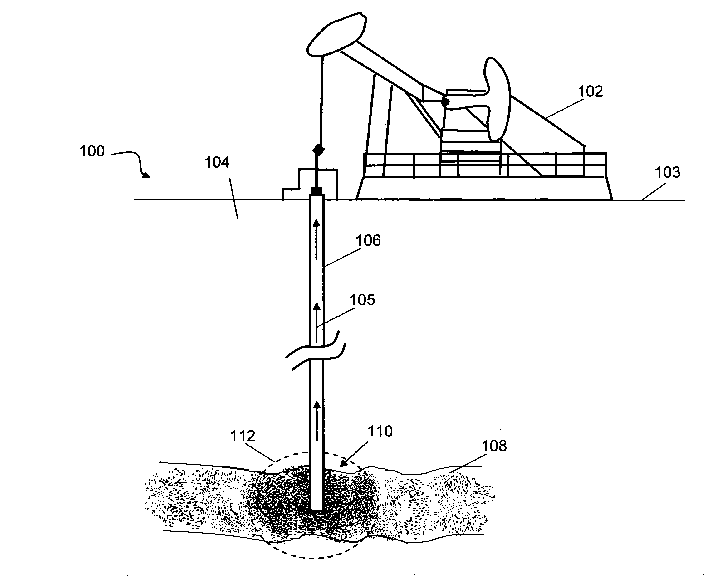
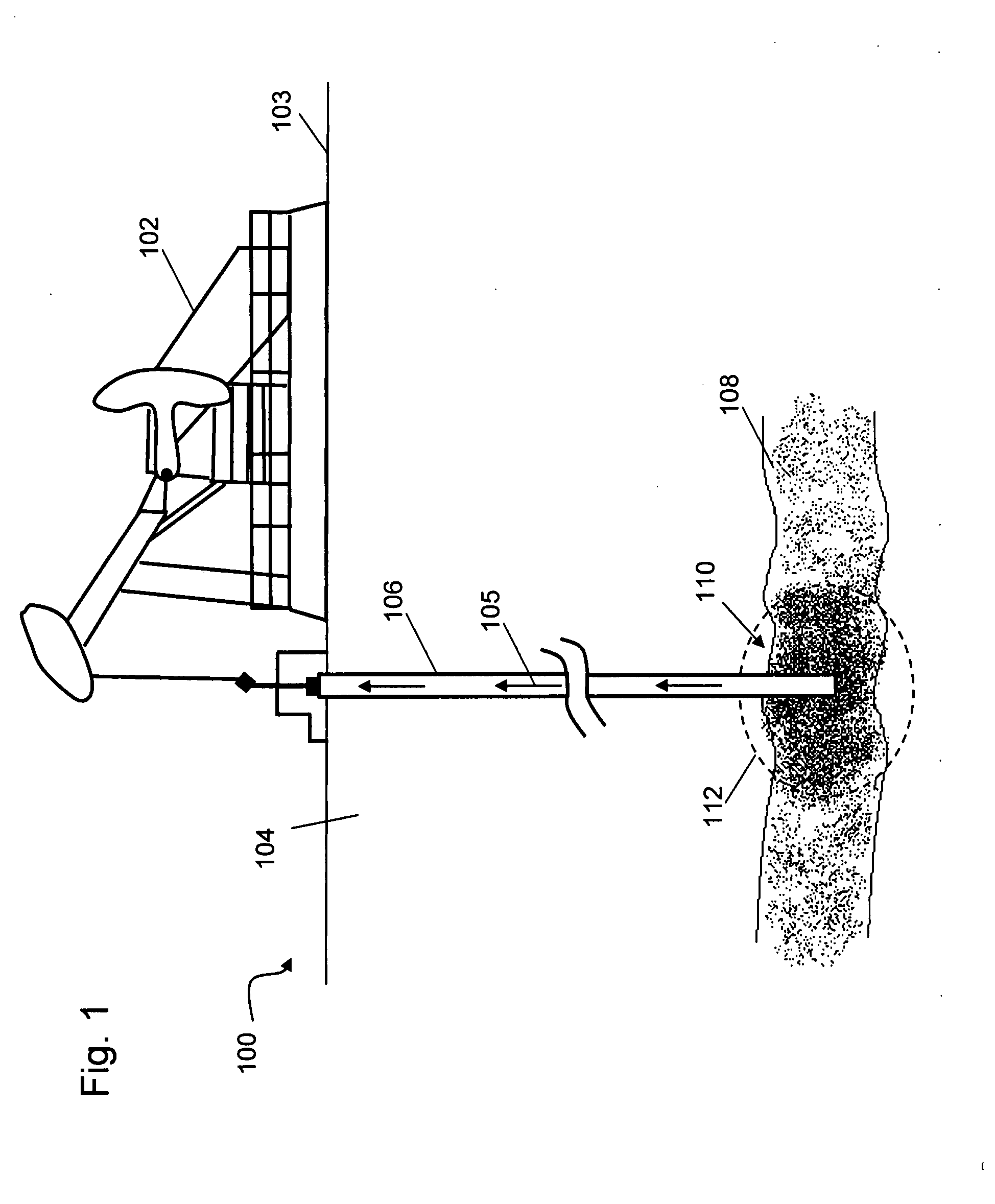
[0053]Referring to FIG. 1, an oil extraction process 100 is depicted where a pumping apparatus 102 located on the surface 103 of ground 104 pumps oil 105 out of an oil well 106 ...


PUM


Abstract

A system and method for reducing resistance to flow in liquid reservoir extraction is provided. A working seal is used to seal an annulus between a well casing and a tubing to create a forcible volume between the working seal and a liquid filled column at the bottom of a well such as an oil well. The working seal may correspond to a wellhead and a Christmas tree. Pressure in the forcible volume is varied to increase the amplitude of the pressure response of the liquid filled column. The pressure may be varied from a maximum positive pressure to a minimum negative pressure in a cyclic manner in a pressure resonation process as controlled by a control system based on measuring the amplitude and phase of the pressure response. Pressure may be supplied to the forcible volume using a pressure supply hose, a pressurized canister associated with the working seal, by a downward stroke of a liquid pumping apparatus, or by controlling the combustion of gases within the forcible volume.

Description

CROSS-REFERENCE TO RELATED APPLICATIONS[0001]This U.S. Non-Provisional patent application claims priority to U.S. Provisional Patent Application No. 60 / 857,702, filed Nov. 8, 2006, which is incorporated herein by reference in its entirety.FIELD OF THE INVENTION[0002]The present invention relates generally to a system and method for reducing resistance to flow in liquid reservoir extraction. More particularly, the present invention relates to a system and method for varying pressure within the steel casing lining an oil well to reduce the resistance to flow caused by damage of the oil bearing formation near the oil well.BACKGROUND OF THE INVENTION[0003]It is desirable to have an improved system and method for reducing resistance to flow in liquid reservoir extraction. An example of liquid reservoir extraction is depicted in FIG. 1, where an oil pumping apparatus extracts oil from an underground oil bearing formation via an oil well. The basics of an oil well are well described by Wik...

Claims


Application Information

Patent Timeline
Patent Type & Authority Applications(United States)
IPC IPC(8): E21B43/18
CPCE21B43/126E21B43/003
Inventor FULLERTON, LARRY W.
Owner GEOSCI INNOVATIONS
Learn More