
Hydraulic system for supplying a hydraulic fluid to a component

a technology of hydraulic fluid and component, which is applied in the direction of positive displacement liquid engines, machines/engines, servomotors, etc., can solve the problems of high energy consumption of pumps, and achieve the effects of less energy consumption, greater oil flow, and short travel distances

Inactive Publication Date: 2008-05-22
LUK LAMELLEN & KUPPLUNGSBAU BETEILIGUNGS KG
View PDF18 Cites 0 Cited by
  • Summary
  • Abstract
  • Description
  • Claims
  • Application Information

AI Technical Summary

Benefits of technology

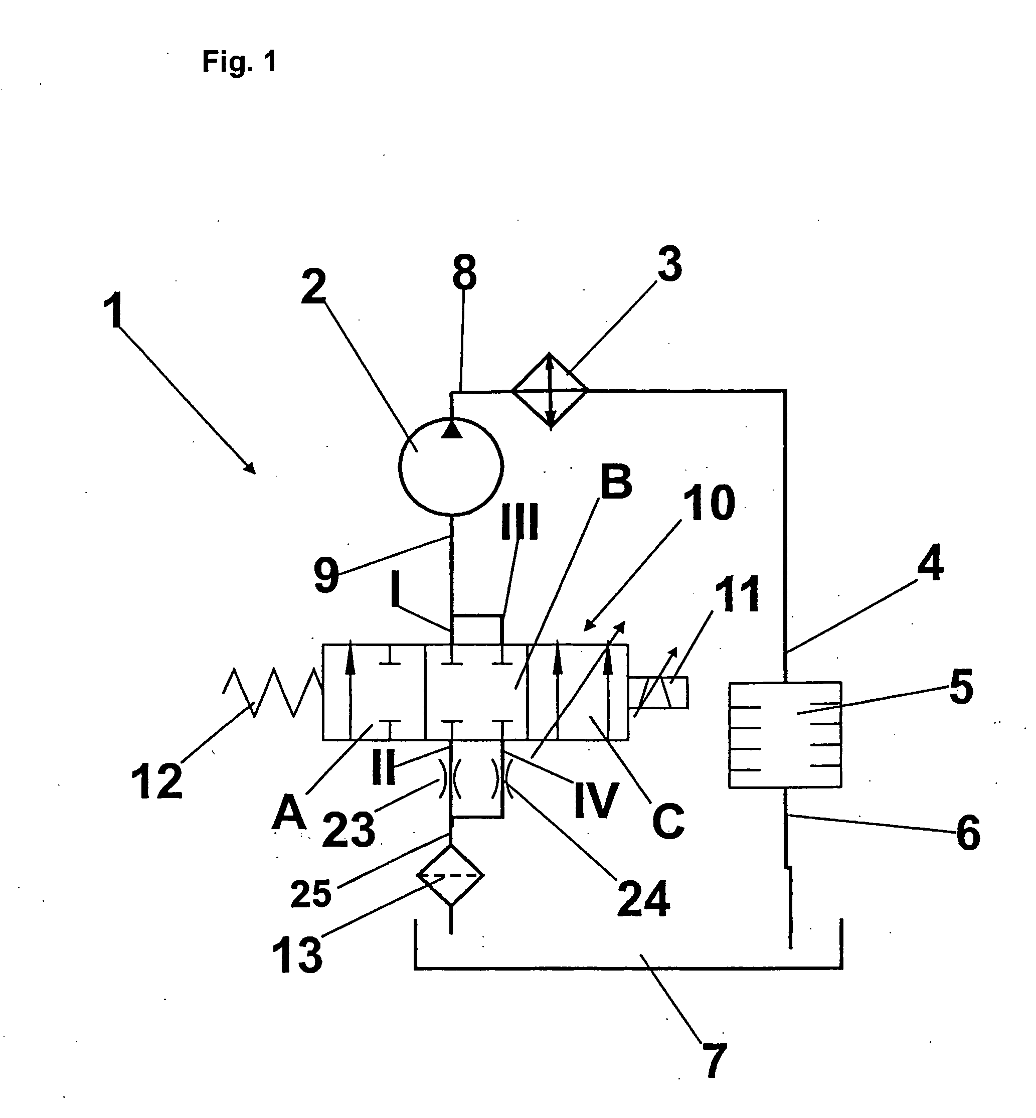
[0010]An advantage of the control valve with a suction restriction is that the pump consumes less energy when the control valve interrupts the supply stream. A conventional solution conveys the entire flow volume against a certain pressure level even when the need for cooling oil is small. With suction throttling, only the amount of oil that is actually employed is brought to pressure.
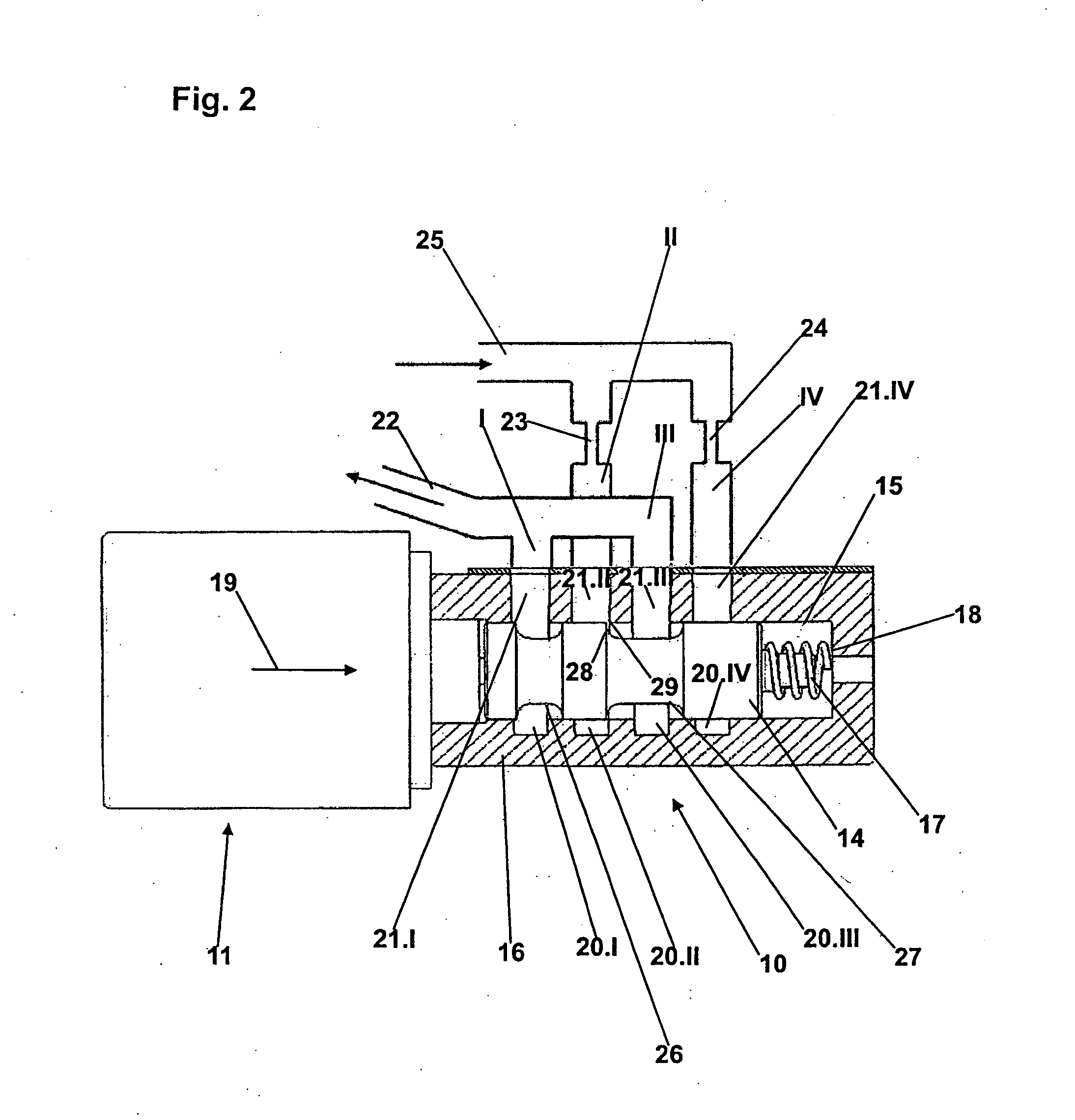
[0011]Since the valve is actuated electromagnetically, only relatively short travel distances are available for the valve spool. The maximum flow volume transported is very high, however. Since the control valve is located at the intake section of the pump (on the suction side), there are no large pressure differentials present that could enable a greater oil flow. In accordance with the invention, the supply channel of the valve is divided into two channels. That makes it possible to utilize the maximum flow per control edge, i.e., to transport about twice the quantity of oil in total. Furthermore, a specially designed restrictor can be integrated into each supply channel as a restriction. Hence a defined quantity of oil can be transported, depending upon whether one channel or both channels are opened.

Problems solved by technology

A disadvantage of known solutions is high energy consumption by the pump, even when, and specifically when, the need for cooling oil is small.

Method used


Image

  • Hydraulic system for supplying a hydraulic fluid to a component
  • Hydraulic system for supplying a hydraulic fluid to a component
  • Hydraulic system for supplying a hydraulic fluid to a component

Examples


Embodiment Construction

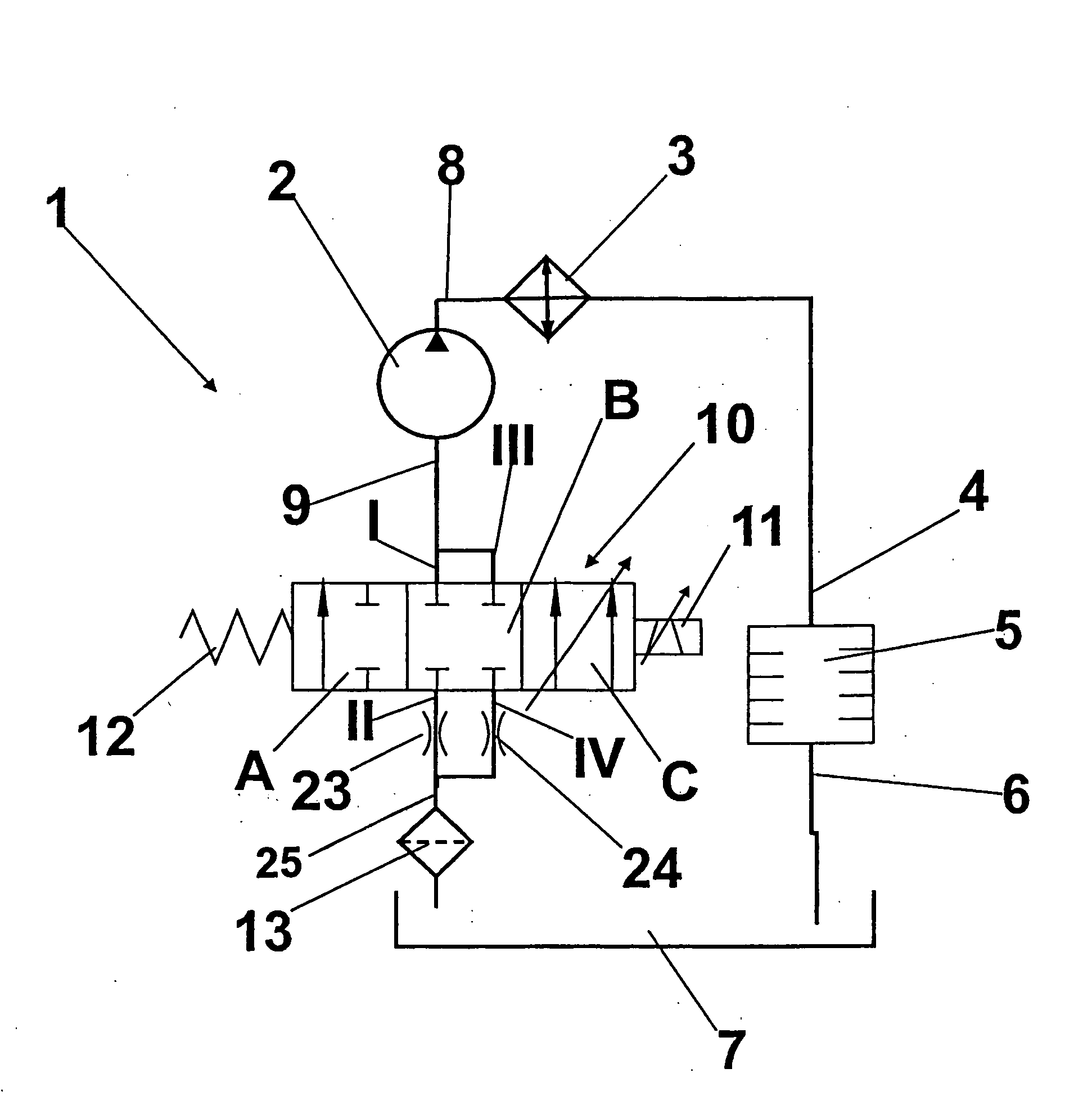
[0018]FIG. 1 is a hydraulic circuit diagram of an exemplary embodiment of a hydraulic system 1 in accordance with the invention. The representation of the control valve 10 corresponds to the customary manner of representation in DIN ISO 1219, in which a valve as such is represented by a rectangle, individual valve positions are represented by squares, connections and hydraulic lines are lines extending from the valves, couplings of the valve connections with each other are represented by arrows within the individual valve positions, blocked connections are represented by a “T.” and a flow restriction is represented by two oppositely-curved lines adjacent to a hydraulic line.

[0019]The hydraulic system 1 includes an electrically driven pump 2, which delivers hydraulic fluid (also referred to below as hydraulic oil, or “oil” for short) through an oil cooler 3 to an oil inlet 4 of a wet clutch 5. From wet clutch 5 the oil used for cooling and lubricating purposes is returned to a reserv...


PUM


Abstract

A hydraulic system for supplying a hydraulic fluid to a hydraulically-operated component. A pump for delivering component the hydraulic fluid from a reservoir is connected with the reservoir through a flow control valve. The control valve is a 4 / 3 directional flow control valve, in which two valve outlet connections are connected to a suction side of the pump and two valve inlet connections are connected to the reservoir. A flow restriction is positioned in each of the conduits extending from the reservoir to the valve inlet connections for reducing the energy consumption of the pump when the need for hydraulic fluid is low.

Description

BACKGROUND OF THE INVENTION[0001]1. Field of the Invention[0002]The present invention relates to a hydraulic system for supplying a hydraulic fluid to a component, as well as to a control valve for use in such a hydraulic system.[0003]2. Description of the Related Art[0004]Suction-throttled oil pumps for wet clutches, specifically for dual clutches, are known from DE 10 2005 027 610 A1, for example. Those are suction-throttled pumps that can serve at least two, and in most cases three, different cooling oil needs of the wet clutch. That necessitates a valve function, which is preferably integrated onto or into the pump. The need for cooling oil during driving operation is covered with a valve position, preferably a basic valve position brought about by a spring. That need is small in comparison to the active cooling needed when accelerating the vehicle from a stop and when shifting the transmission. For active cooling when driving off and when shifting, a different valve position is...

Claims


Application Information

Patent Timeline
Patent Type & Authority Applications(United States)
IPC IPC(8): F15B13/04
CPCF16D2048/0209F04B49/225F16D48/02F16D25/123F04B2205/171
Inventor STAUDINGER, MARTINMULLER, ERIC
Owner LUK LAMELLEN & KUPPLUNGSBAU BETEILIGUNGS KG
Learn More