
Quantum optical coherence tomography data collection apparatus and method for processing therefor

a tomography and optical coherence technology, applied in the field of three-dimensional imaging techniques, can solve the problems of reducing the depth resolution capability of oct, the subject of oct, and the inherently low contrast of the signal of interest, so as to eliminate or reinforce the effect of coincident detection

Inactive Publication Date: 2005-04-19
TWIN PHOTON
View PDF2 Cites 71 Cited by
  • Summary
  • Abstract
  • Description
  • Claims
  • Application Information

AI Technical Summary

Benefits of technology

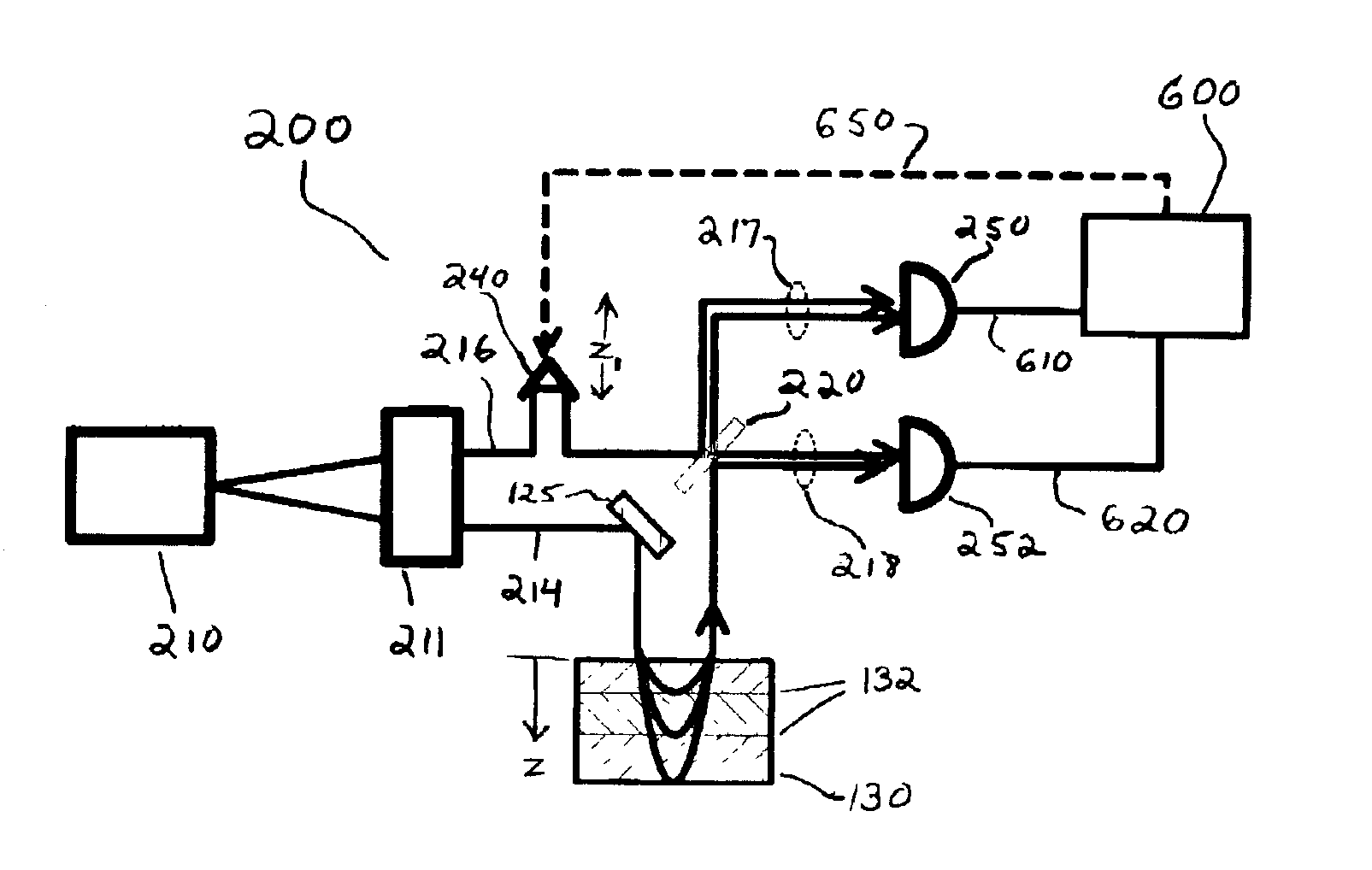
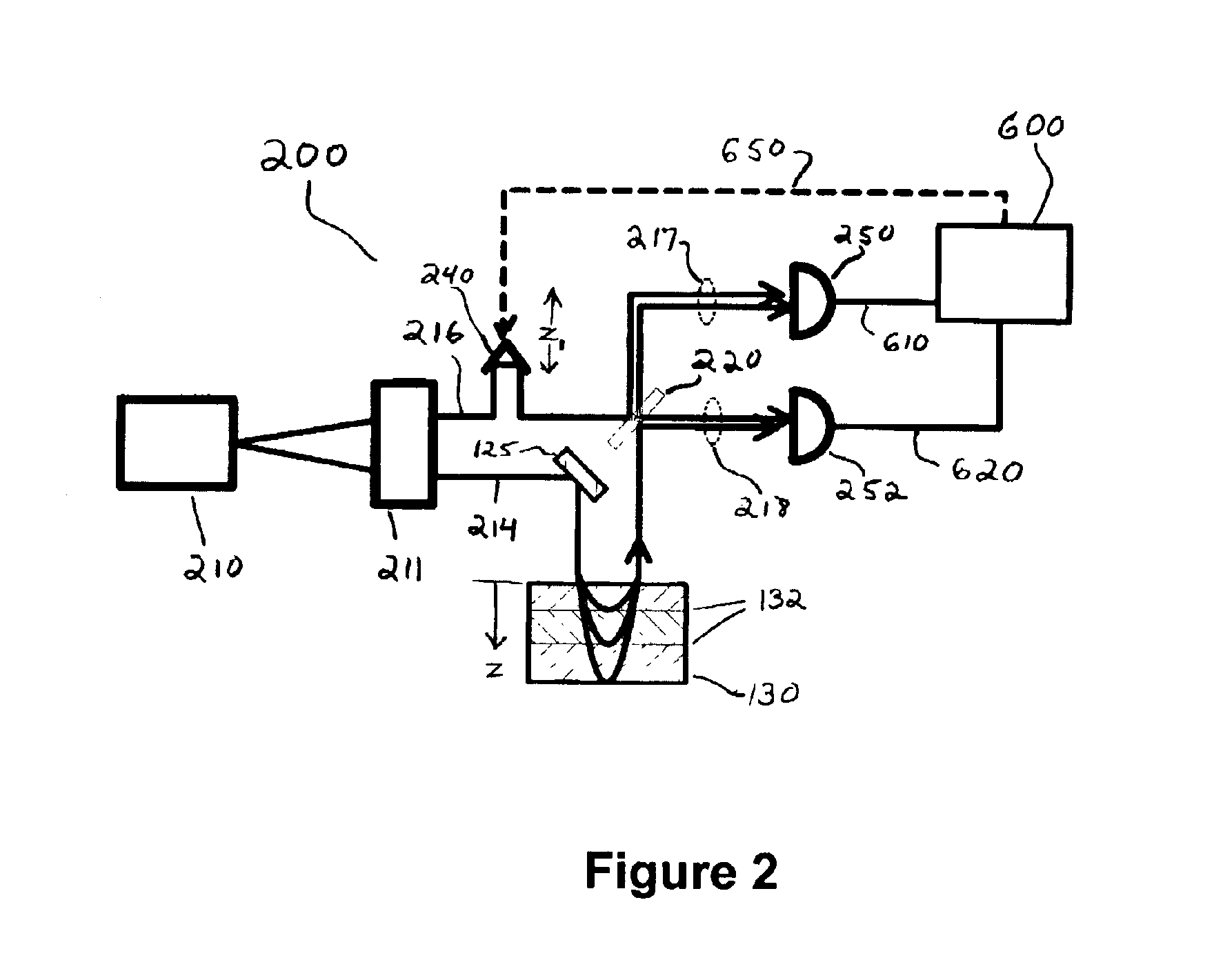
[0012]The significance of CD's in entangle photon interference has been well established in the literature and is described by three of the present inventors in the '149 application. Summarily, the key to the invention is understanding that each twinon is a single entity that happens to be made up of two photons. The behavior of one photon is correlated with the behavior of the other, even when they appear to be in separate locations. When a twinon traverses an optical system in which there are multiple indistinguishable paths, quantum optical interference determines in which of the paths the photons will be detected. For example, destructive interference can prevent two different detectors from observing a photon simultaneously while quantum optical constructive interference can “force” one photon to appear at each detector. Thus, in the absence of any differential delay (viz., difference between the delay induced by propagating to different depths in the semi-reflective object and the delay introduced intentionally by the VTE) between the two twin photons, quantum-interference effects can either eliminate or reinforce coincident detections (“CD's”) on two separated detectors. Therefore, a dip or peak in the CD rate relative to the mean value is an indication that the time delay in the paths leading to the two detectors has been equalized.

Problems solved by technology

OCT is subject to two significant limitations; first, the signal of interest is inherently low contrast since the modulated interference signal rides on a non-modulated self interference background.
Secondly, optical dispersion in the object reduces the depth resolution capability of OCT; basically dispersion changes the optical path length within the object as a function of wavelength, which in turn makes the different wavelengths that make up the short coherence length light appear to be coming from different physical depths within the object.

Method used


Image

  • Quantum optical coherence tomography data collection apparatus and method for processing therefor
  • Quantum optical coherence tomography data collection apparatus and method for processing therefor
  • Quantum optical coherence tomography data collection apparatus and method for processing therefor

Examples


Embodiment Construction

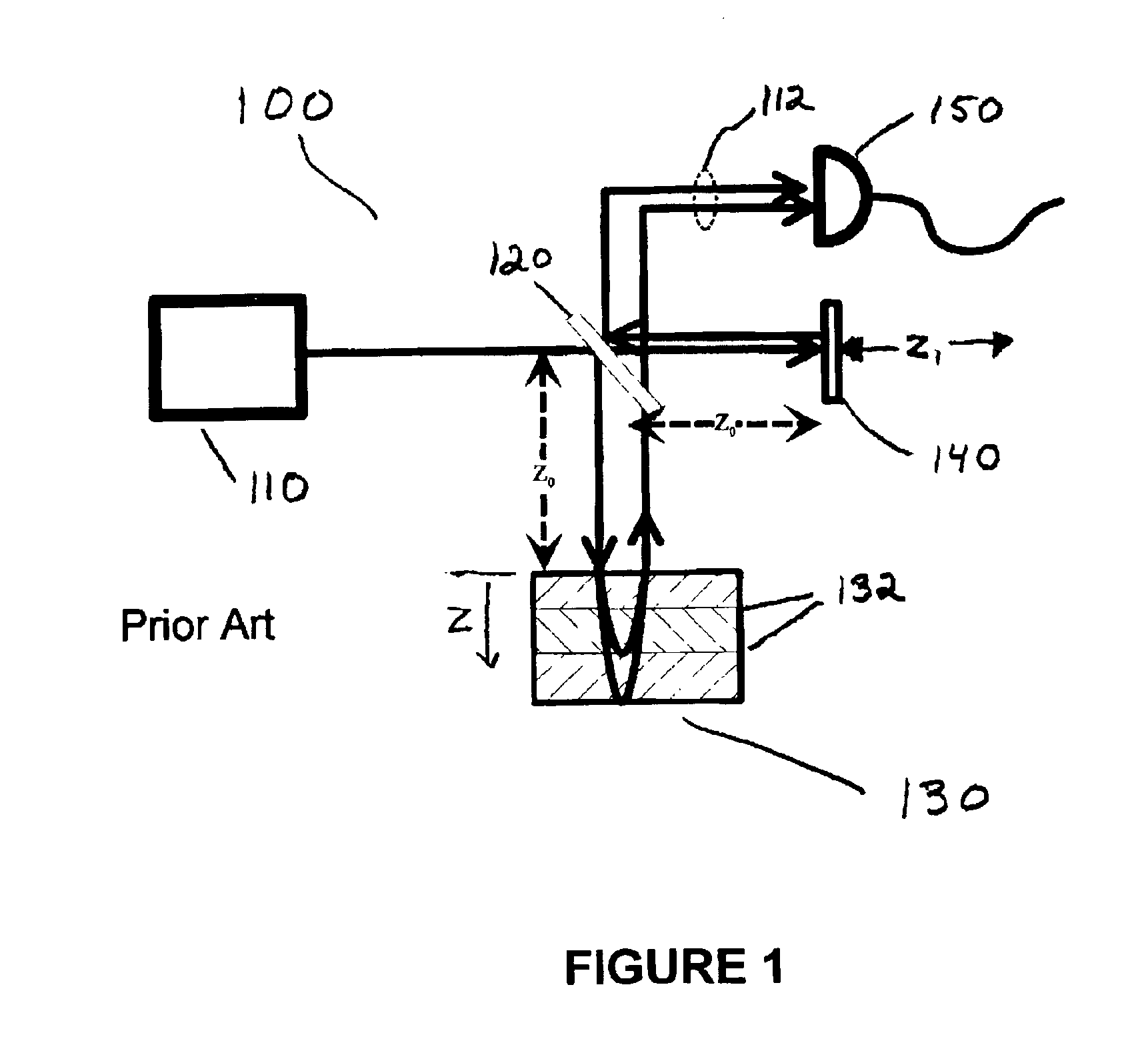
[0024]Optical coherence tomography (OCT) is a technique for probing the depth (“z”) reflectance profile of semi-reflective objects, for example biologic tissue, in the same sense that SONAR can probe the thermal layers of the ocean using sound reflectance. SONAR is a first order effect, meaning it measures the strength of the returning signal as a function of time, so it requires transmission of a short temporal ping to achieve depth resolution. Because light travels so much faster than sound a first order light measurement is impractical in thin samples; therefore, OCT uses a second order effect, meaning it measures the interference strength between the probe and a scanned reference signal. OCT achieves depth resolution by using short coherence length radiation. The present invention, Quantum OCT (QOCT), is a fourth order effect, meaning it measures the quantum optical interference statistically observed in a beam of so-called entangled photons. The operation of the QOCT imager is ...


PUM


Abstract

The disclosed Quantum Optical Coherence Tomography apparatus and method includes a source of quantum entangled photons and a quantum interference device. The pair of entangled photons is divided into two beams, one of which illuminates a semi-reflective object and the second of which is reflected from a variable optical time-delay element (VTE). The VTE is scanned and the quantum interference in the QID is recorded to build up a reflectance profile of the object. A real scanning produces a full tomographic reflectance image. A method of processing the data to eliminate the effects of optical dispersion is disclosed.

Description

CROSS-REFERENCE TO RELATED APPLICATIONS[0001]Not applicableSTATEMENT REGARDING FEDERALLY SPONSORED RESEARCH OR DEVELOPMENT[0002]Not applicableREFERENCE TO COMPACT DISK APPENDIX[0003]Not applicableBACKGROUND OF THE INVENTION[0004]The present invention generally relates to the field of three-dimensional imaging techniques in general and, more particularly, to optical tomography and to Optical Coherence Tomography in specific. Tomography in general is a technique for building up a full three-dimensional image of a non-planar object out of a series of two-dimensional image slices through that object. Perhaps the most popular example of this technique is X-Ray Computed Axial Tomography (CAT) scanning where the object is most easily observed from the “sides”; that is, the object generally has only one long dimension and two relatively short dimensions (like a human body) However, another technique, Optical Coherence Tomography (OCT) has become a versatile and useful tool in fields such as...

Claims


Application Information

Patent Timeline
Patent Type & Authority Patents(United States)
IPC IPC(8): G01B9/02
CPCG01B9/02007G01B9/02091G01B9/02088G01B2290/45G01B2290/55G01B2290/70
Inventor TEICH, MALVIN C.SALEH, BAHAA E A.SERGIENKO, ALEXANDER V.ABOURADDY, AYMAN F.NASR, MAGUED B.
Owner TWIN PHOTON
Learn More