
Image pickup apparatus

a technology of image pickup and optical system, which is applied in the direction of picture signal generators, solid-state device signal generators, television systems, etc., can solve the problems of difficult to form a high-performance image pickup optical system using a simple lens, and obstacle to miniaturization of the image pickup optical system, and achieves small size and high image quality.

Inactive Publication Date: 2005-04-19
CANON KK
View PDF31 Cites 69 Cited by
  • Summary
  • Abstract
  • Description
  • Claims
  • Application Information

AI Technical Summary

Benefits of technology

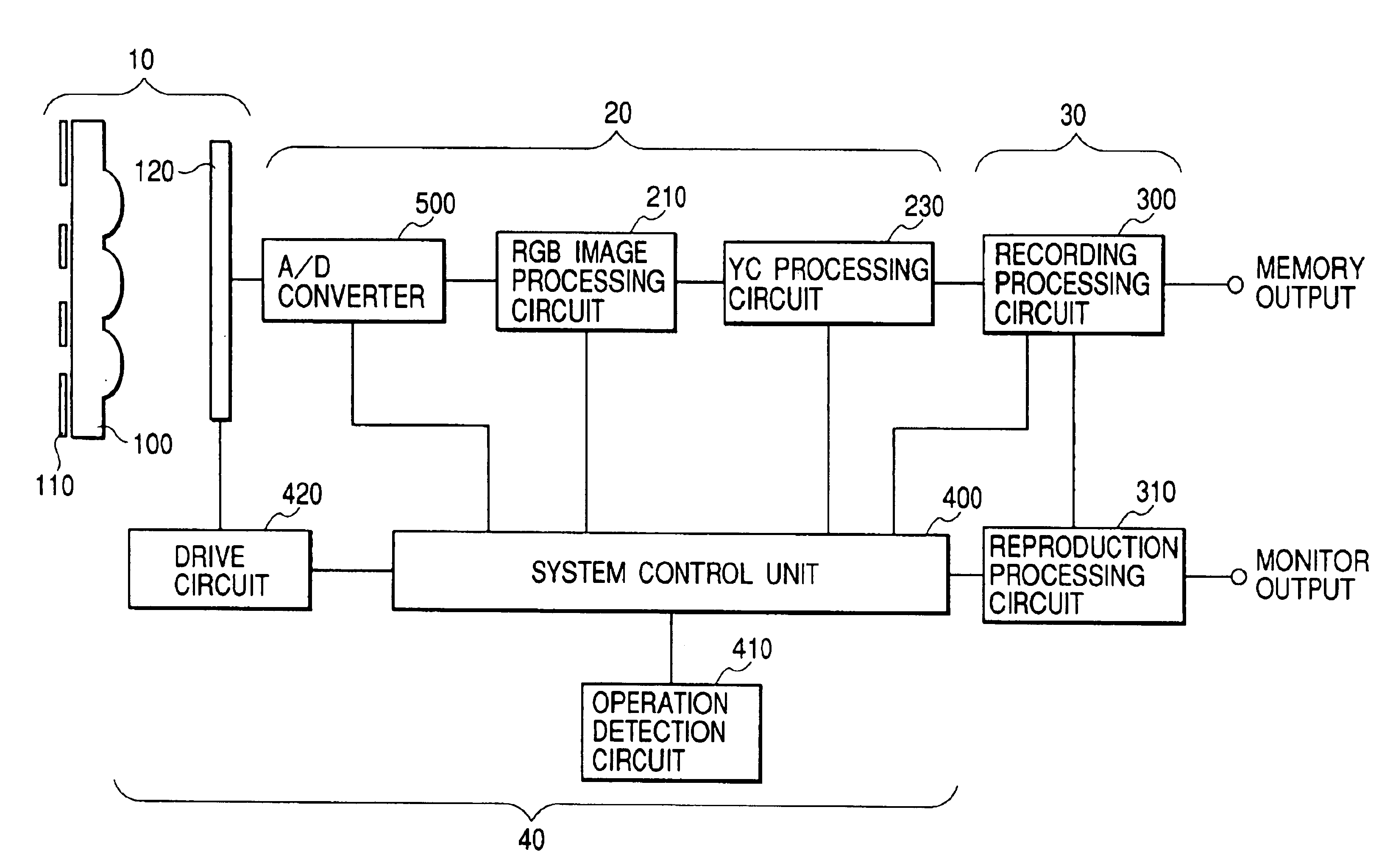
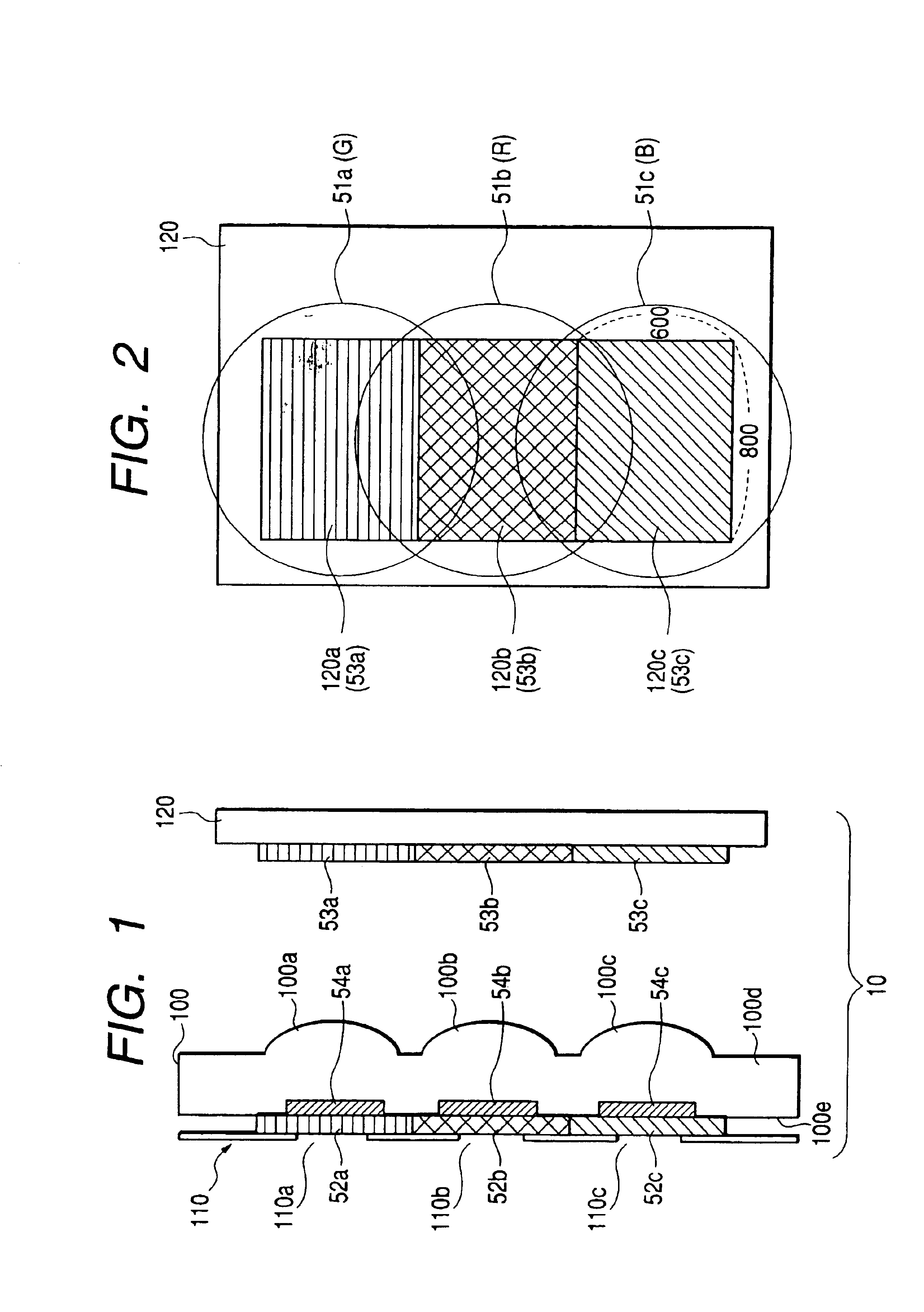
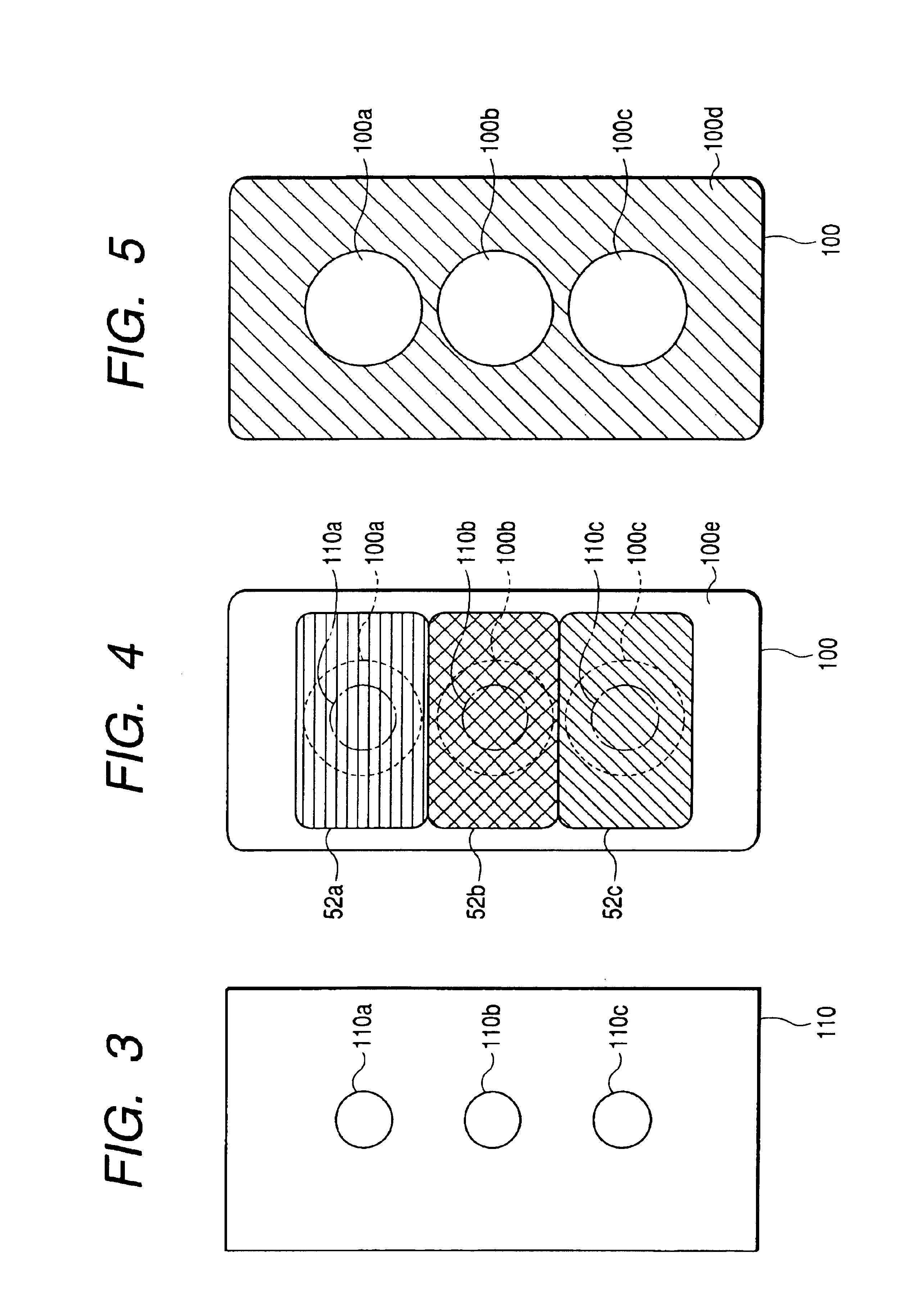
[0008]According to one aspect of the present invention, there is provided an image pickup apparatus comprising first and second image pickup portions for receiving at least a first wavelength component of object light and a second wavelength component of the object light different from the first wavelength component, respectively, and first and second optical systems for guiding the first and second wavelength components of the object light to be received by the first and second image pickup portions to the first and second image pickup portions, respectively, via different optical paths, the first and second optical systems being constructed such that the focal length of the first optical system with regard to the first wavelength component is equal to the focal length of the second optical system with regard to the second wavelength component. The present invention can result in an image pickup apparatus which is small-sized and has high image quality.

Problems solved by technology

As a result, it is difficult to form a high performance image pickup optical system using a simple lens.
This is an obstacle to miniaturization of the image pickup optical system.

Method used


Image

  • Image pickup apparatus
  • Image pickup apparatus
  • Image pickup apparatus

Examples


Embodiment Construction

[0027]Preferred embodiments of the present invention are now described in detail with reference to the drawings.

[0028]FIGS. 17A, 17B, and 17C illustrate the overall structure of a digital color camera according to a first embodiment of the present invention. FIGS. 17A, 17C, and 17B are a front view, a rear view, and a sectional view taken along the line 17B—17B in the rear view of FIG. 17C, respectively.

[0029]In FIGS. 17A, 17B, and 17C, reference numeral 1 denotes a camera body. An illuminating light intake window 2 formed of a white diffusing plate is positioned at the back of a color liquid crystal monitor 4. Reference numerals 5 and 6 denote a main switch and a RELEASE button, respectively. Reference numerals 7, 8, and 9 are switches for a user to set the state of the camera. In particular, the reference numeral 9 denotes a PLAY button. A reference numeral 13 denotes a display of the remaining number of recordable pictures. Object light which is incident into a prism 12 from a vi...


PUM


Abstract

An image pickup apparatus is provided having first and second image pickup portions for receiving at least first and second distinct wavelength components of object light, respectively, and first and second optical systems for guiding the first and second wavelength components to the first and second image pickup portions, respectively, via different optical paths. The first and second optical systems are formed to have respective shapes so that the focal length of the first optical system with regard to the first wavelength component is equal to the focal length of the second optical system with regard to the second wavelength component. When a virtual object distance, as defined as set forth herein, an interval between optical axes of the first and second optical systems is set such that a change in an interval between object images of the first and second wavelength components received by the first and second image pickup portions, respectively, between when an object exists at the virtual object distance and when it exists at infinity is smaller than a pixel pitch of the image pickup portions multiplied by two.

Description

BACKGROUND OF THE INVENTION[0001]1. Field of the Invention[0002]The present invention relates to an image pickup apparatus capable of picking up a dynamic image or a still image such as a video camera.[0003]2. Related Background Art[0004]In a digital color camera, in response to depressing a RELEASE button, an object image is exposed to a solid-state image pickup element such as a CCD or a CMOS sensor for a desired time period, an image signal thus obtained is converted into a digital signal, and then is subject to predetermined processing such as YC processing, and an image signal of a predetermined format is obtained. This digital image signal is recorded in a semiconductor memory. The recorded image signal can be read according to the need to be reproduced as a signal capable of being displayed or printed, and can be output to a monitor or the like to visualize the recorded image.[0005]Three methods are known for exposing an object image. One is a method in which RGB color filter...

Claims


Application Information

Patent Timeline
Patent Type & Authority Patents(United States)
IPC IPC(8): H04N9/04
CPCH04N9/045H04N23/55H04N25/41H04N23/843H04N25/6153H04N25/136
Inventor SUDA, YASUO
Owner CANON KK
Learn More