
Battery-driven electronic device and mobile communication apparatus

a technology of electronic devices and batteries, applied in the direction of cell components, process and machine control, instruments, etc., can solve the problems of large battery capacity of the above-described conventional lithium ion batteries, low battery voltage, and large battery voltage change ratios, etc., to achieve good efficiency

Inactive Publication Date: 2005-04-19
PANASONIC CORP
View PDF9 Cites 52 Cited by
  • Summary
  • Abstract
  • Description
  • Claims
  • Application Information

AI Technical Summary

Benefits of technology

[0019]It is an object of the present invention to provide a battery-driven electronic device that allows a long term use of a battery and can be used with batteries having various discharge characteristics, and mobile communications equipment in which such a battery-driven electronic device is mounted.
[0046]Thus, the step-down converter in the rear stage can operate with such a good efficiency that the second switching means is constantly on, when the load requires the maximum voltage and the maximum current.

Problems solved by technology

However, although battery-driven electronic devices have become more compact and high performance and there is a demand for improvement in compactness and large capacity of batteries, that is, improvement in energy density, the theoretical limit is almost reached in terms of large capacity for the above-described conventional lithium ion batteries.
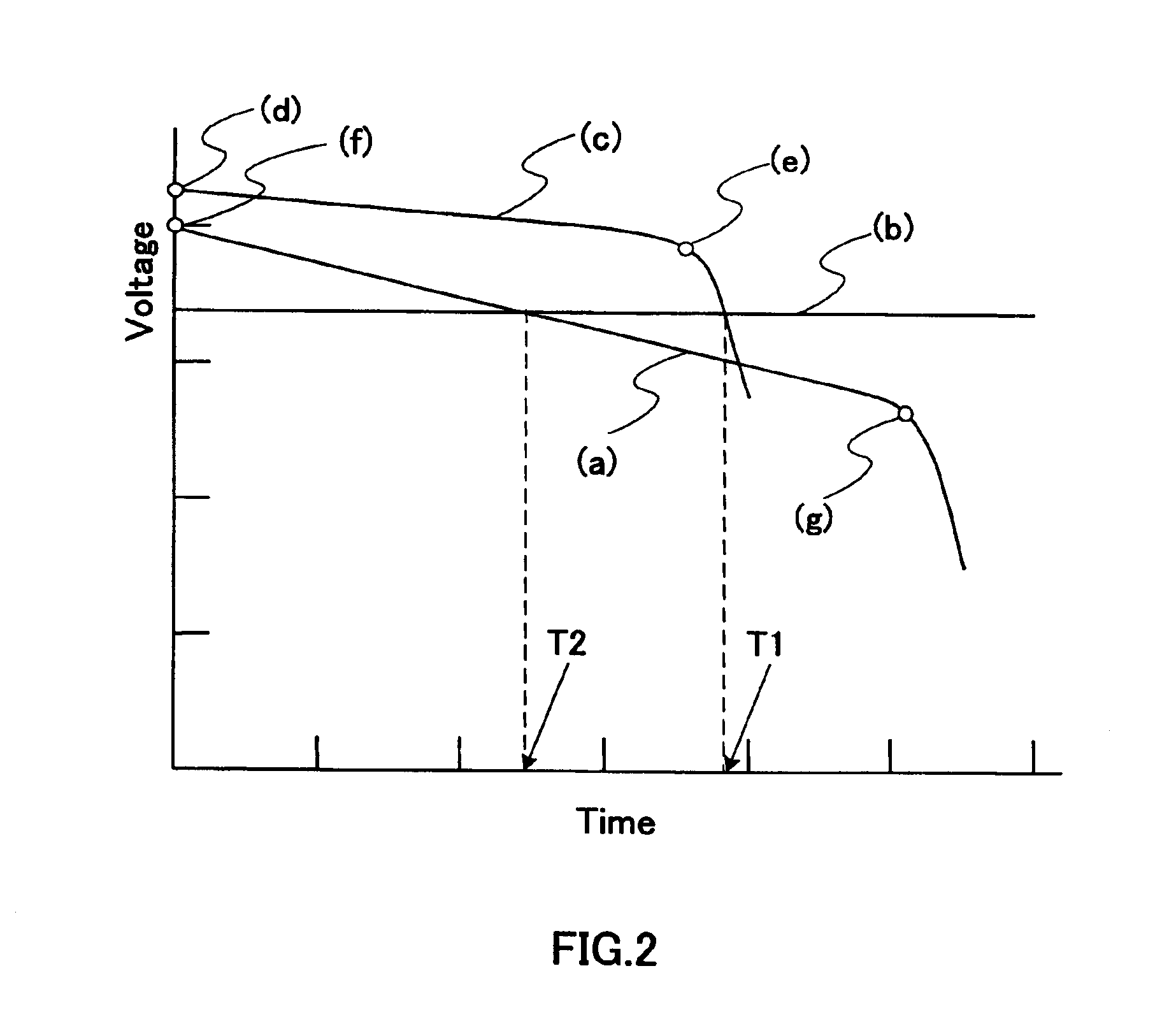
However, the batteries made of a material that can realize a high energy density have problems in that the average battery voltage is lower and the battery voltage change ratio is larger than those of the conventional lithium ion batteries.
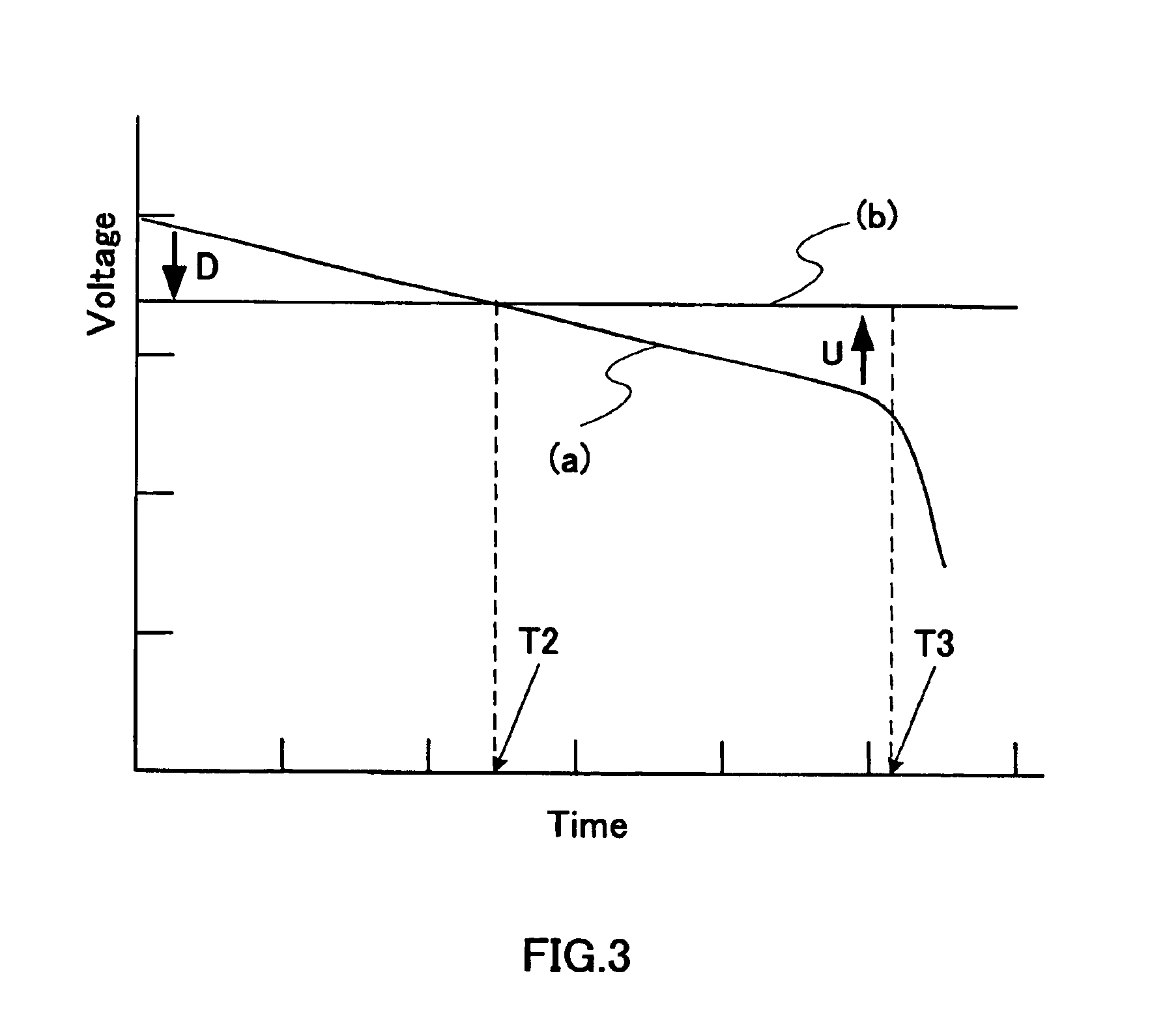
When the lithium ion battery employing such a new material is incorporated into equipment in which the conventional lithium ion battery is used, and the supply voltage required by the load in the electronic device is between the rated charge end voltage and the rated discharge end voltage of the battery, then the following problem arises.
However, the voltage difference between the input and the output becomes large, so that it is difficult to realize high efficiency of the step-down converter, and the input voltage is increased.
Therefore, it is necessary to increase the withstand voltage of capacitors or semiconductors, and therefore the efficiency is further decreased and the components become larger so that compactness cannot be achieved.

Method used


Image

  • Battery-driven electronic device and mobile communication apparatus
  • Battery-driven electronic device and mobile communication apparatus
  • Battery-driven electronic device and mobile communication apparatus

Examples


first embodiment

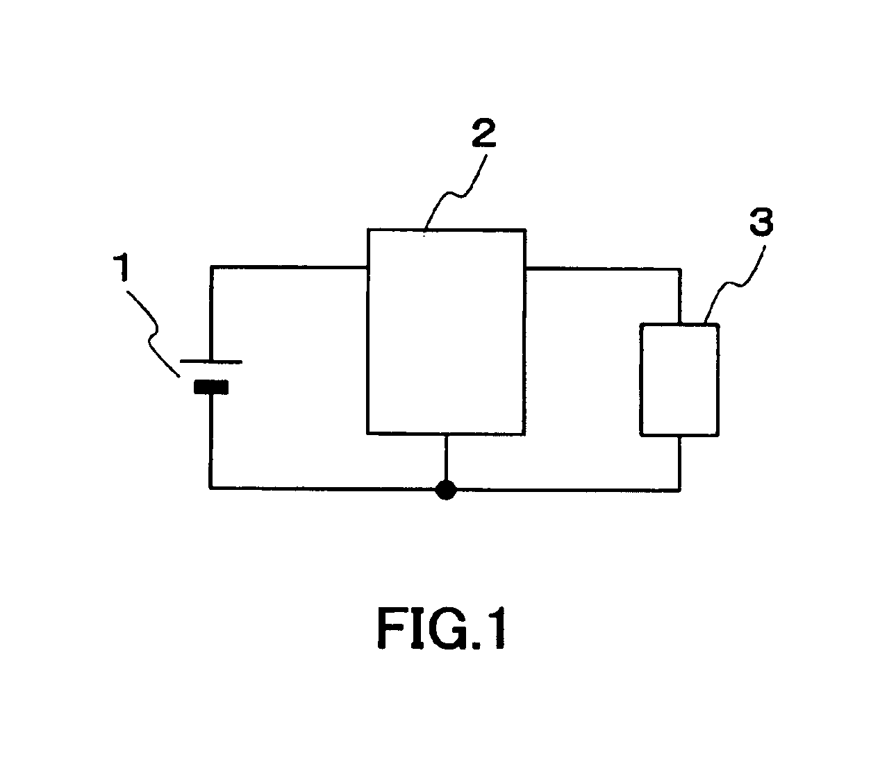
[0068]FIG. 1 is a circuit block diagram showing a schematic configuration of a battery-driven electronic device according to a first embodiment of the present invention. In FIG. 1, reference numeral 1 denotes a battery employing lithium cobaltate as the positive electrode, graphite as the negative electrode, and a nonaqueous solvent containing lithium supporting electrolyte as the electrolyte and having discharge characteristics that are sloped over time with a battery voltage change ratio of 0.25 or more, as opposed to the conventional lithium ion battery having an average battery voltage of 3.7 V at room temperature as the discharge characteristics. Herein, the “battery voltage change ratio” refers to a value obtained by dividing a voltage difference (Ec−Ed) by Ec, where Ec is the open circuit voltage after the rated charge end voltage is reached, and Ed is the open circuit voltage after the rated discharge end voltage is reached.

[0069]Reference numeral 2 denotes a step-up and -do...

second embodiment

[0095]FIG. 8 is a diagram showing the configuration of a battery-driven electronic device and mobile communications equipment according to a second embodiment of the present invention. This embodiment is configured such that the load includes a power amplifier for wireless transmission that sends a burst-like signal as in the time-division multiplex system. In FIG. 8, reference numeral 21 denotes a battery having the profile that the power density is higher than that of a battery having a commonly used composition, but the discharge characteristics are sloped over time. Reference numeral 22 denotes a step-up and -down converter using the battery 21 as the input. Reference numeral 23 denotes a power amplifier to which the output voltage of the step-up and -down converter is input. Reference numeral 25 denotes an input terminal of the power amplifier 23, and reference numeral 26 denotes an output terminal of the power amplifier 23. Reference numeral 24 denotes controlling means for pe...

third embodiment

[0099]FIG. 9 is a configuration diagram of a battery-driven electronic device and mobile communications equipment according to a third embodiment of the present invention. This embodiment is configured such that the load includes a power amplifier for wireless transmission of the CDMA (Code Division Multiple Access) system. In FIG. 9, reference numeral 21 denotes a battery having a profile that the power density is higher than that of a battery having a commonly used composition, but the discharge characteristics are sloped over time. Reference numeral 22 denotes a step-up and -down converter to which the output voltage of the battery 21 is input, and reference numeral 23 denotes a power amplifier using the output voltage of the step-up and -down converter as the supply voltage. Reference numeral 25 denotes an input terminal of the power amplifier 23, and reference numeral 26 denotes an output terminal of the power amplifier 23. Reference numeral 24 denotes controlling means for con...


PUM

PropertyMeasurementUnit
battery voltageaaaaaaaaaa
diameteraaaaaaaaaa
current densityaaaaaaaaaa

Abstract

The present invention provides a battery-driven electronic device for which a long time use of the battery can be achieved and mobile communications equipment such as a portable telephone. Even if the time at which the output voltage of a battery 201 becomes below the supply voltage required by a load 206 including a power amplifier for wireless communications comes earlier than a conventional lithium ion battery because of its discharge characteristics that the battery voltage change ratio is 0.25 or more, a step-up and -down converter 200 operates as follows. When the output voltage of the battery is higher than the supply voltage required by the load, the voltage is set to a predetermined supply voltage by the step-down operation mode. When the output voltage of the battery is decreased and becomes lower than the supply voltage required by the load, the voltage is set to a predetermined supply voltage by the step-up operation mode. Thus, even for a battery employing a new material having a high energy density, a long term use of the battery can be achieved.

Description

TECHNICAL FIELD[0001]The present invention relates to a battery-driven electronic device employing a battery as its input source and mobile communications equipment such as portable telephones and portable communications terminals in which such a battery-driven electronics device is mounted.BACKGROUND ART[0002]For wireless communications devices, information terminals and other electronic devices employing batteries as their power source for which the convenience of portability is required, there is a demand for a long time use after charging when the battery is a secondary battery or after battery exchange when the battery is a primary battery, in addition to compactness and lightweightness.[0003]The configuration shown in FIG. 19 commonly is used for such a battery-driven electronic device. As shown in FIG. 19, a conventional battery-driven electronic device uses as its input source a battery typified by a conventional lithium ion battery, more specifically, a battery 401 employin...

Claims


Application Information

Patent Timeline
Patent Type & Authority Patents(United States)
IPC IPC(8): H02M3/158H02M3/155H02J7/00H02M3/04
CPCH02J7/0065H02M3/1582H02M3/155Y02B60/50H02J2207/20
Inventor HANDA, HIROYUKIISHII, TAKUYANAKAJIMA, YASUFUMIBITO, YASUHIKOKASAMATSU, SHINJINITTA, YOSHIAKI
Owner PANASONIC CORP
Learn More