
Method for improving capacitor noise and mismatch constraints in a semiconductor device

a technology of capacitor noise and mismatch constraints, which is applied in the field of capacitor design, can solve the problems of limiting the minimum capacitance value that can be used, increasing power consumption and/or reducing the speed of the integrated circuit,

Inactive Publication Date: 2005-04-12
NORTH STAR INNOVATIONS +1
View PDF11 Cites 30 Cited by
  • Summary
  • Abstract
  • Description
  • Claims
  • Application Information

AI Technical Summary

Benefits of technology

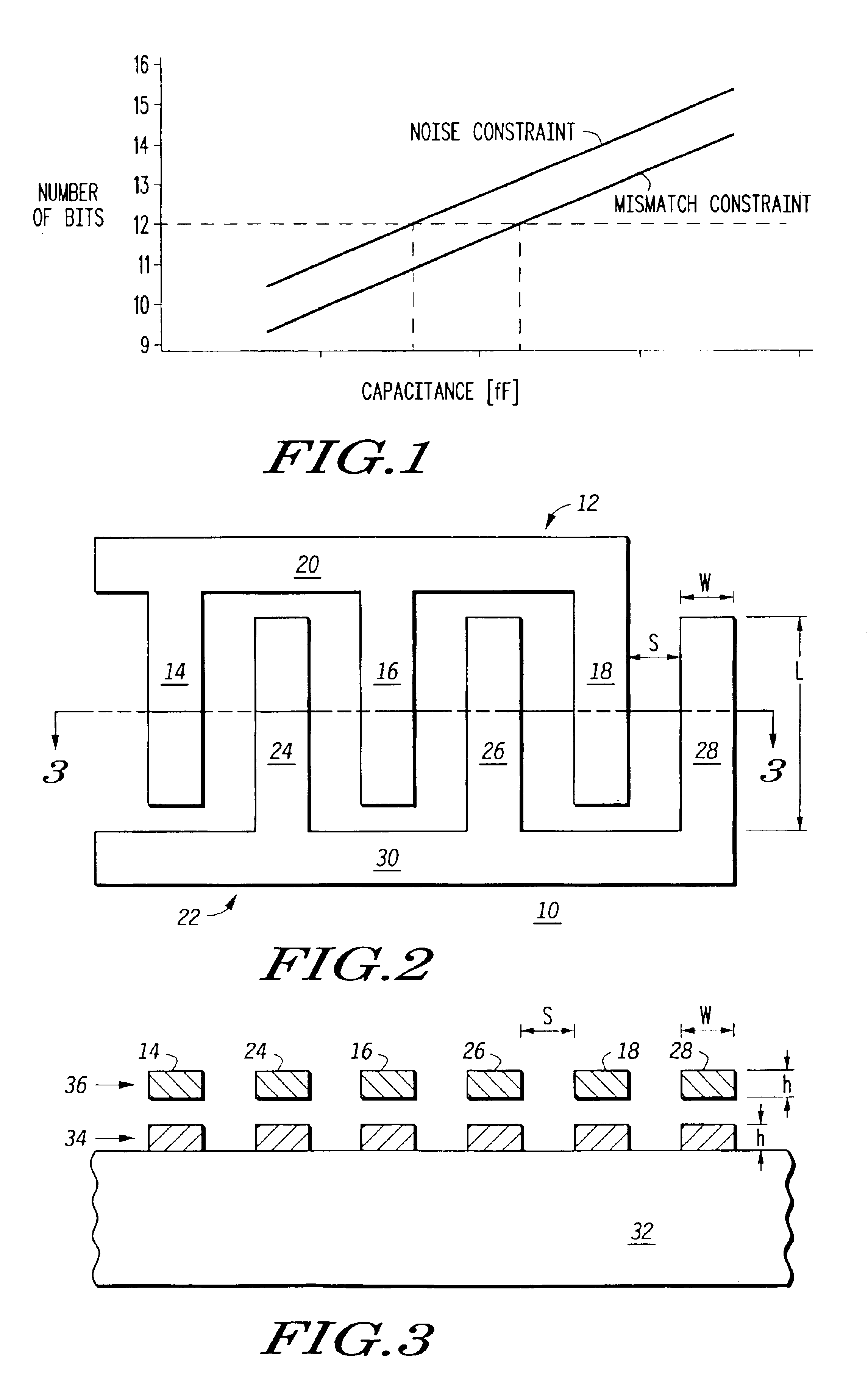
It has been determined through experimentation that for a given fringe capacitor, mismatch is determined primarily by the surface area of the capacitor and is not determined by capacitance. Also, the noise limitation is dependent on capacitance. For a given fringe capacitor layout, mismatch can be improved by increasing finger spacing while maintaining a predetermined surface area. The predetermined surface area is maintained by removing fingers from the fringe capacitor design. Therefore, the size of the fringe capacitor is determined to satisfy both mismatch and noise constraints for the switched capacitor design. By maintaining the layout area of the capacitor and adjusting finger spacing, the capacitance density can be lowered to shift the mismatch constraint to be consistent with the noise constraint. In addition to improving the mismatch constraint, lowering the capacitance of a switched capacitor design provides the advantages of reduced power consumption and / or increased speed. In addition, increasing finger spacing provides the added advantages of improving particle defect robustness and improving reliability.

Problems solved by technology

However, for fringe capacitors used in switched capacitor circuits, noise and mismatch constraints limit the minimum capacitance value that can be used.
Both of these constraints are process dependent, with the mismatch constraint typically dominating the noise constraint and requiring a larger capacitance value than the noise constraint, thus increasing power consumption and / or reducing speed of the integrated circuit.

Method used


Image

  • Method for improving capacitor noise and mismatch constraints in a semiconductor device
  • Method for improving capacitor noise and mismatch constraints in a semiconductor device
  • Method for improving capacitor noise and mismatch constraints in a semiconductor device

Examples


Embodiment Construction

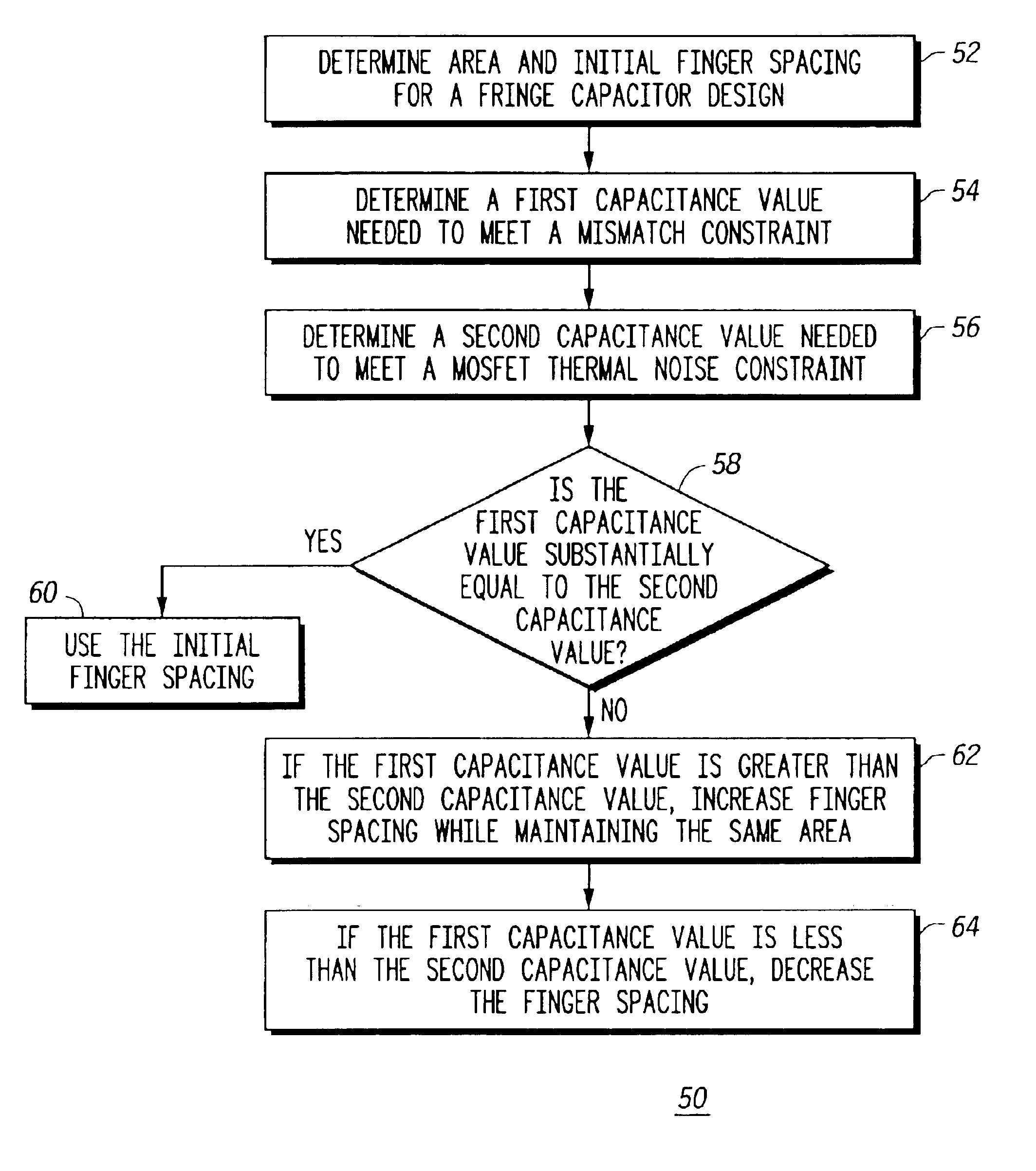
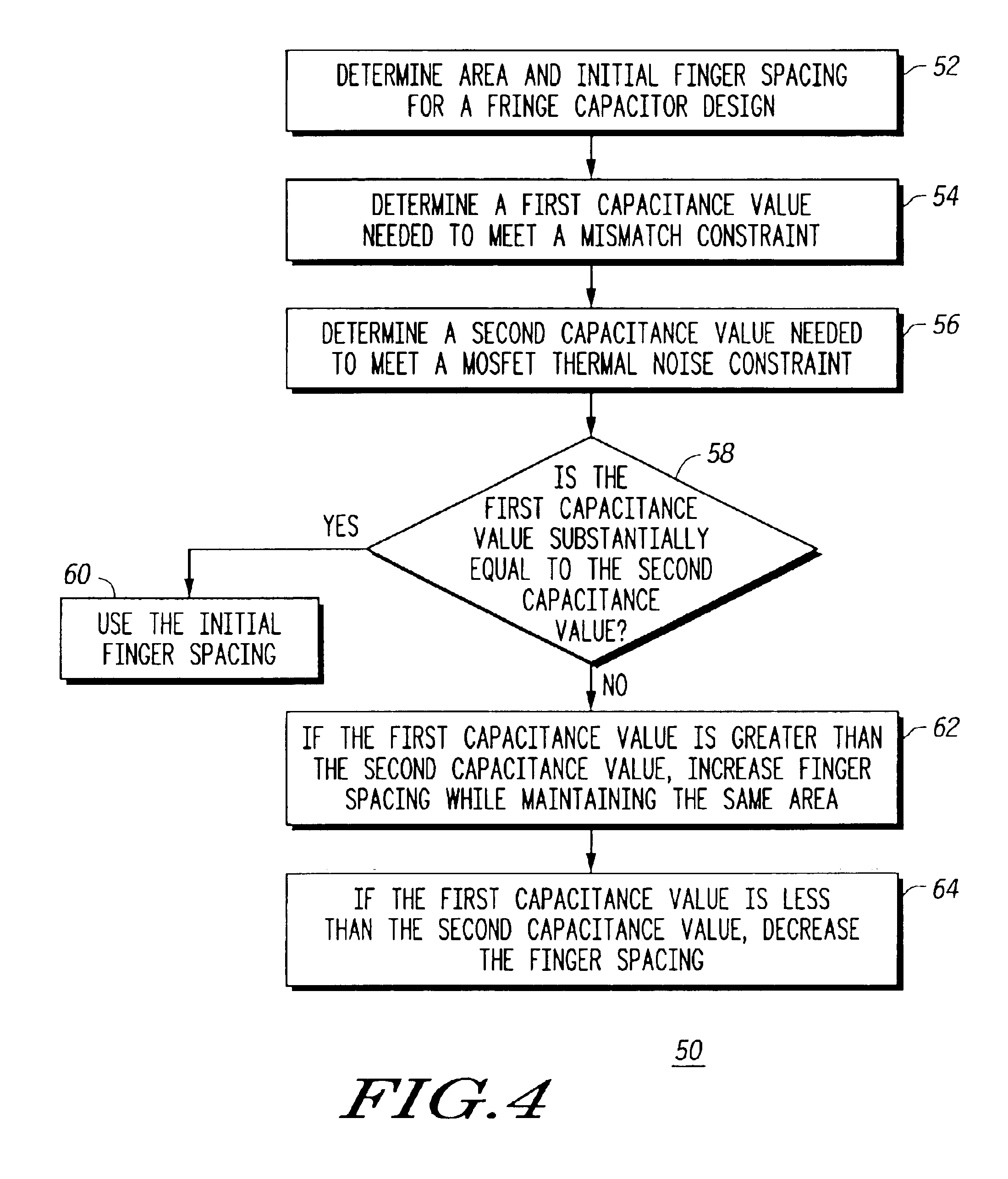
Generally, the present invention provides, in one embodiment, a method for improved switched capacitor performance by lowering a mismatch constraint to be equal to, or nearly equal to, a noise constraint. The mismatch constraint is lowered by increasing a finger spacing of a fringe capacitor design while maintaining the same area of the fringe capacitor. In another embodiment, a noise constraint is lowered by decreasing finger spacing. Lowering the mismatch constraint reduces the capacitance value of the fringe capacitor. Lowering the noise constraint reduces the area of the fringe capacitor, thereby reducing the parasitic capacitance, the chip size and the cost to manufacture an integrated circuit having the fringe capacitor. Both configurations may be used in, for example, and an analog-to-digital converter.

The size of a capacitor in a switched capacitor design is determined by several factors. Two of these factors are mismatch and noise. A noise limitation, or constraint, comes f...


PUM


Abstract

In one embodiment, a method (50) is provided for improving switched capacitor performance by lowering a mismatch constraint to be equal to, or nearly equal to, a noise constraint. The mismatch constraint is lowered by increasing a finger spacing of a fringe capacitor design (10) while maintaining the same surface area covered by the fringe capacitor design (10). In another embodiment, a noise constraint is lowered by decreasing finger spacing. Lowering the noise constraint by decreasing finger spacing reduces the area of a fringe capacitor used in, for example, an analog-to-digital converter. Both embodiments may improve performance of the analog-to-digital converter by lowering power consumption, increasing speed, or both.

Description

FIELD OF THE INVENTIONThe present invention relates generally to capacitor design, and more particularly, to a method for improving capacitor noise and mismatch constraints in a semiconductor device having a fringe capacitor.BACKGROUND OF THE INVENTIONCapacitors are used in many integrated circuit applications, such as for example, switched capacitors in analog-to-digital converters (ADCs). There are many ways to implement integrated circuit capacitors. The “fringe” capacitor is one type of integrated circuit capacitor that is widely used because it provides good capacitance density.Two desirable attributes of many integrated circuit designs, including ADCs are low power consumption and / or high speed operation. Therefore, it would be desirable to size the capacitors used in ADCs as small as possible. However, for fringe capacitors used in switched capacitor circuits, noise and mismatch constraints limit the minimum capacitance value that can be used. The noise constraint is determin...

Claims


Application Information

Patent Timeline
Patent Type & Authority Patents(United States)
IPC IPC(8): G06F17/50
CPCG06F17/5063G06F30/36
Inventor DRENNAN, PATRICK G.
Owner NORTH STAR INNOVATIONS
Learn More