
Dialyzing apparatus

a dialysis apparatus and dialysis technology, applied in the field of dialysis apparatus, can solve the problem of low cost of each dialysis operation, and achieve the effect of efficient water removal

Inactive Publication Date: 2005-04-12
OMRON HEALTHCARE CO LTD
View PDF13 Cites 18 Cited by
  • Summary
  • Abstract
  • Description
  • Claims
  • Application Information

AI Technical Summary

Benefits of technology

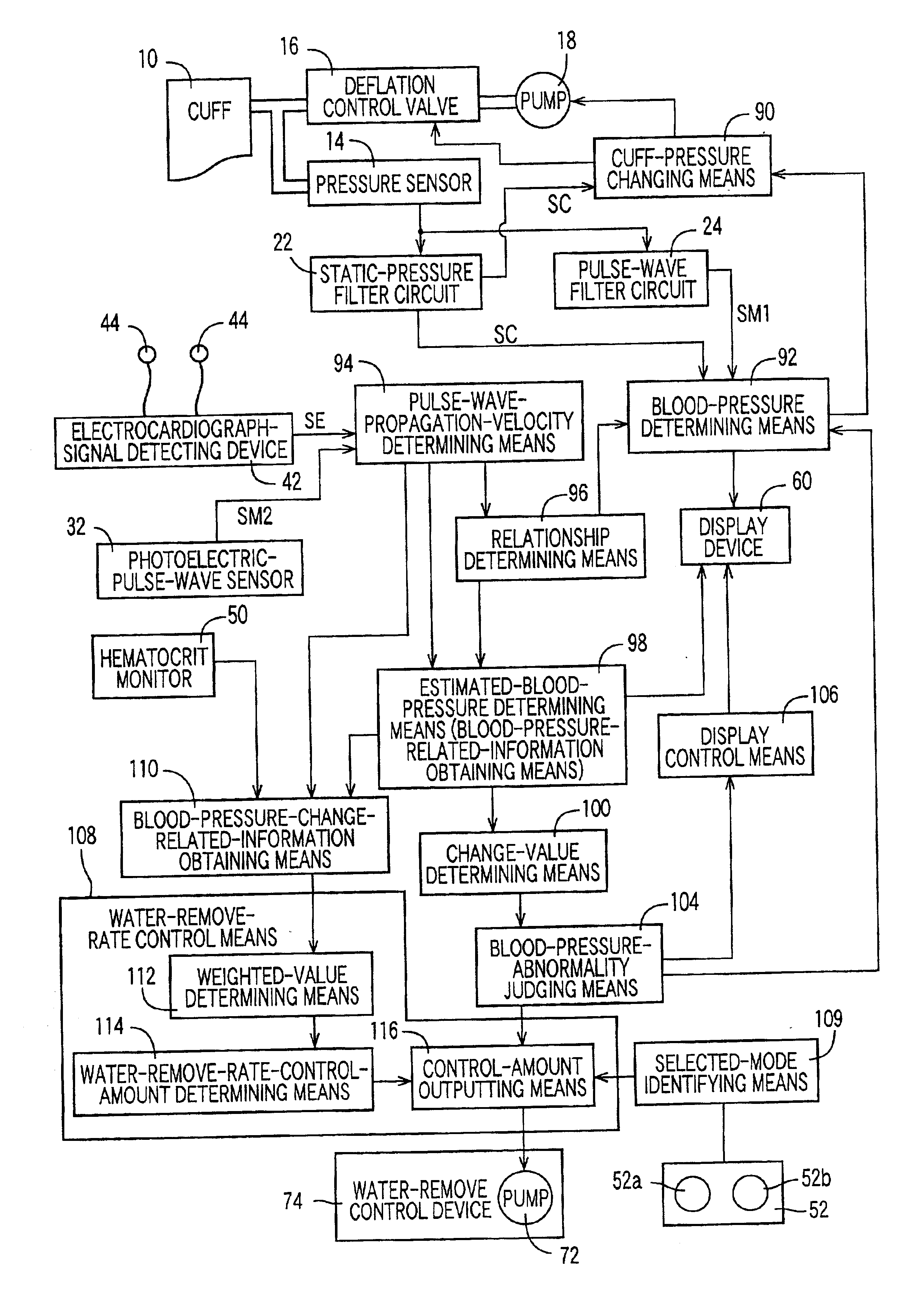
It is therefore an object of the present invention to provide a dialyzing apparatus which can automatically control a water-remove rate so as to efficiently remove water from blood of a patient, without causing an abrupt blood-pressure decrease in the patient.
Since the blood-pressure-change-related-information obtaining device obtains a plurality of sorts of blood-pressure-change-related information each of which is related to a change (e.g., a decrease) of a blood pressure of the patient during the dialysis operation, and the water-remove-rate control device controls the water-remove rate of the dialyzer based on the plurality of sorts of blood-pressure-change-related information. Thus, the present apparatus can automatically control the water-remove rate so as to efficiently remove water from blood of the patient, without causing an abrupt blood-pressure decrease in the patient. Therefore, a skillful medical specialist such as a doctor need not adjust the water-remove rate so frequently, and consequently only a relatively small number of medical specialists are needed as compared with a number of dialyzing apparatuses used, and additionally each dialysis operation costs low.
Preferably, the blood-pressure-change-related-information obtaining device obtains a blood-flow parameter that reflects a flow rate of a blood of the patient; an autonomic-nerve parameter that reflects an activity of an autonomic nerve of the patient; a blood-vessel parameter that reflects a degree of expansion of a blood vessel of the patient; and a blood-viscosity parameter that reflects a viscosity of the blood of the patient and, based on those parameters, the water-remove-rate control device controls the water-remove rate. Thus, the present apparatus can operate the dialyzer at an appropriate water-remove rate that corresponds to the blood flow rate, autonomic-nerve activity, blood-vessel expansion degree, and blood viscosity of the patient that are closely related to a blood-pressure decrease of the patient during the dialysis operation. Accordingly, the present apparatus can efficiently remove water from the blood of the patient, without causing an abrupt blood-pressure decrease in the patient.
Preferably, the water-remove-rate control device comprises a weighted-value determining means for determining, for each of the plurality of sorts of blood-pressure-change-related information, a weighted value corresponding to a change of said each sort of blood-pressure-change-related information; a water-remove-rate-control-amount determining means for determining a water-remove-rate control amount based on a sum of the respective weighted values determined for the plurality of sorts of blood-pressure-change-related information; and a control means for controlling the water-remove rate of the dialyzer, according to the water-remove-rate control amount determined by the water-remove-rate-control-amount determining means. Since the weighted-value determining means determines, for each of the plurality of sorts of blood-pressure-change-related information, a weighted value corresponding to a change of the each sort of blood-pressure-change-related information, and the control means controls the water-remove rate of the dialyzer, according to a water-remove-rate control amount determined based on a sum of the respective weighted values determined for the plurality of sorts of blood-pressure-change-related information. Thus, the present apparatus can more efficiently remove water from the blood of the patient, without causing an abrupt blood-pressure decrease in the patient.

Problems solved by technology

Therefore, a skillful medical specialist such as a doctor need not adjust the water-remove rate so frequently, and consequently only a relatively small number of medical specialists are needed as compared with a number of dialyzing apparatuses used, and additionally each dialysis operation costs low.

Method used


Image

  • Dialyzing apparatus
  • Dialyzing apparatus
  • Dialyzing apparatus

Examples


Embodiment Construction

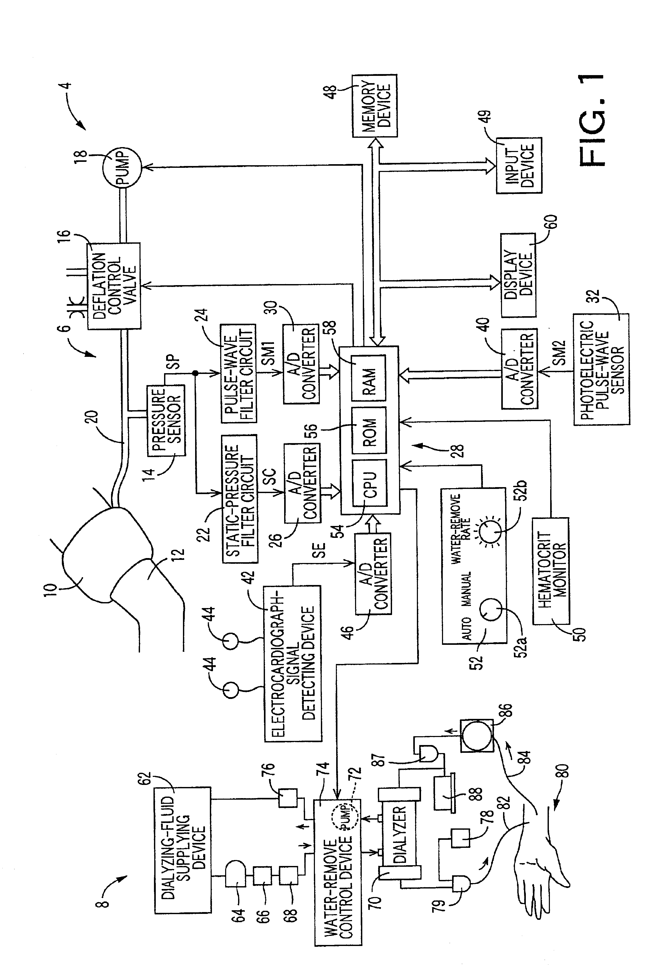
Hereinafter, there will be described an embodiment of the present invention, by reference to the drawings. FIG. 1 is a diagrammatic view for explaining a construction of a dialyzing apparatus 4 to which the present invention is applied. The dialyzing apparatus 4 includes a measurement section 6 and a dialysis section 8. First, the measurement section 6 will be described below.

In FIG. 1, reference numeral 10 designates a blood-pressure measuring cuff which includes a belt-like cloth bag and a rubber bag accommodated in the cloth bag and which is wound around an upper portion 12 of one arm of a patient that is not connected to a dialyzer 70, described later. The cuff 10 is connected to a pressure sensor 14, a deflation control valve 16, and an air pump 18 via a piping 20. The deflation control valve 16 is selectively placed in a pressure-supply position in which the control valve 16 permits a pressurized air to be supplied from the air pump 18 to the cuff 10, a slow-deflation position...


PUM

PropertyMeasurementUnit
Viscosityaaaaaaaaaa

Abstract

A dialyzing apparatus includes a dialyzer which removes water from blood of a patient at a water-remove rate during a dialysis operation, a blood-pressure-change-related-information obtaining device which obtains a plurality of sorts of blood-pressure-change-related information each of which is related to a change of a blood pressure of the patient during the dialysis operation, and a water-remove-rate control device which controls the water-remove rate of the dialyzer, based on the plurality of sorts of blood-pressure-change-related information, according to a predetermined control manner.

Description

BACKGROUND OF THE INVENTION1. Field of the InventionThe present invention relates to a dialyzing apparatus which can automatically control a water-remove rate so as to efficiently remove water from blood of a patient, without causing an abrupt blood-pressure decrease in the patient.2. Related Art StatementThere is known a dialyzing apparatus which artificially removes, by utilizing osmotic-pressure difference or ultrafiltration, urea, uric acid, or creatinine, together with water, from blood of a patient. When the dialyzing apparatus is used, a patient whose blood circulates through the apparatus, and a doctor who observes the patient cannot move away from the apparatus, for at least several hours. Therefore, it is desired to increase the water-remove rate and thereby quickly finish the dialysis operation. However, if the water-remove rate is too high, the patient may fall in a shock. To avoid this, an appropriate water-remove rate is manually set so as to allow a target water amoun...

Claims


Application Information

Patent Timeline
IPC IPC(8): A61M1/14
CPCA61M1/14A61M2230/04A61M2230/20A61M2230/005
Inventor KAWAGUCHI, KEIZOH
Owner OMRON HEALTHCARE CO LTD
Learn More