
Air precleaner and method for separating heavier-than-air particulate debris from debris laden air

a technology of air precleaner and air filter, which is applied in the direction of filtration separation, combustion-air/fuel-air treatment, and separation processes, etc. it can solve the problems that the known precleaner may not provide satisfactory performance, and achieve the effect of increasing the rotational velocity of the vortex flow, facilitating the removal of debris, and increasing the life of the air filter

Inactive Publication Date: 2005-04-12
SY KLONE
View PDF19 Cites 49 Cited by
  • Summary
  • Abstract
  • Description
  • Claims
  • Application Information

AI Technical Summary

Benefits of technology

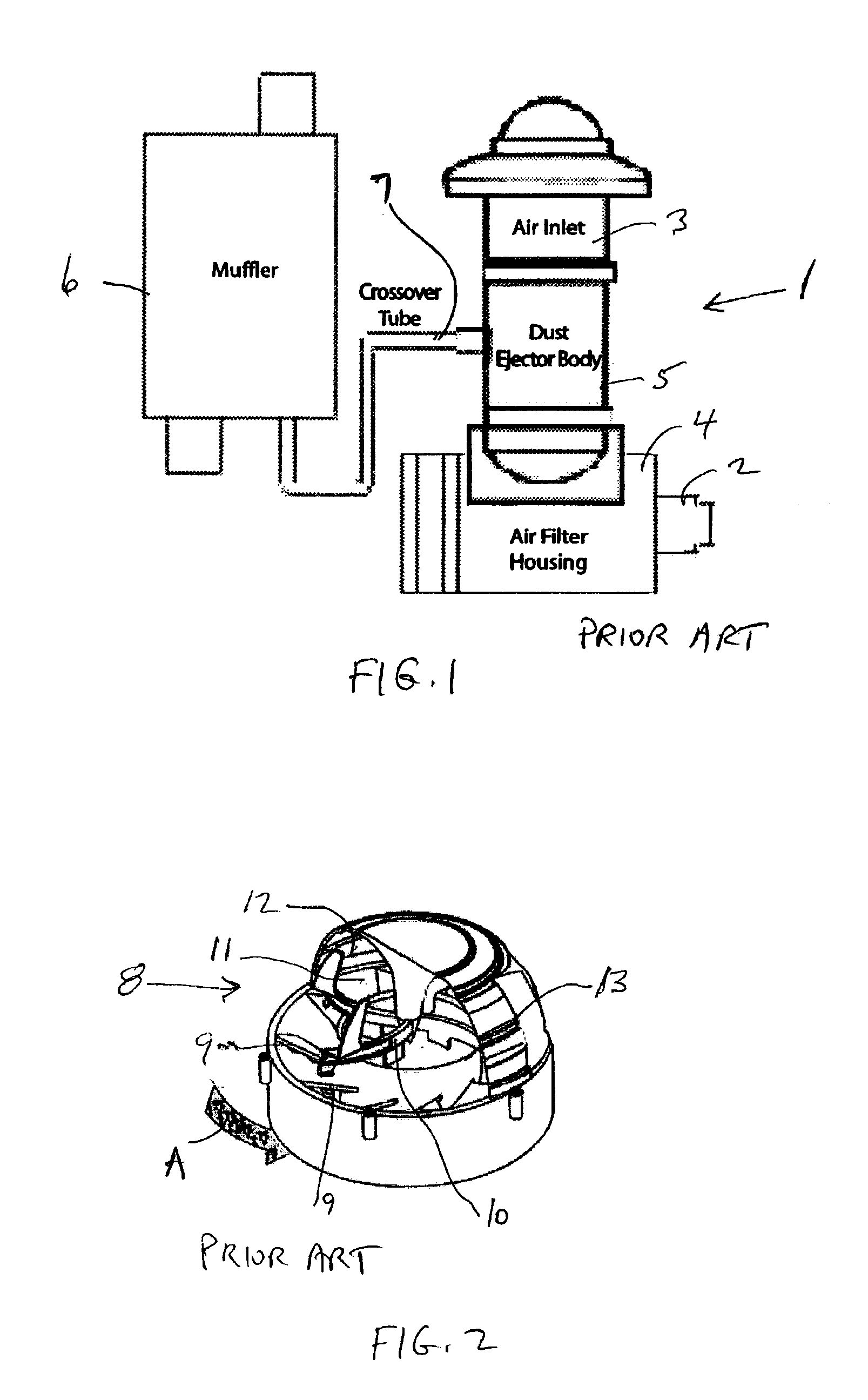
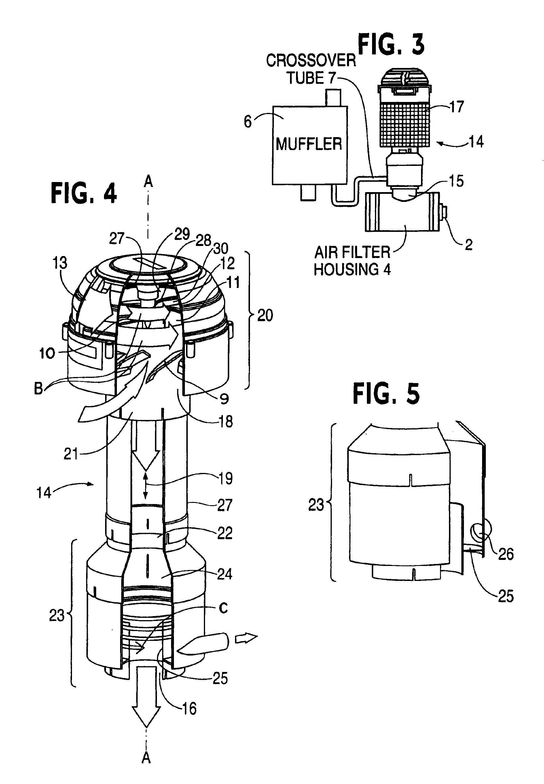
The air precleaner of FIG. 2 offers improved performance compared with that in FIG. 1. However, it has been found that in extreme conditions, such as found in many landfill and transfer station operations, the known precleaners may fail to provide satisfactory performance. The present invention solves this problem by combining the benefits of both ejective and scavenger based systems to achieve outstanding performance and substantial improvement in air filter life when operating under these extreme conditions.
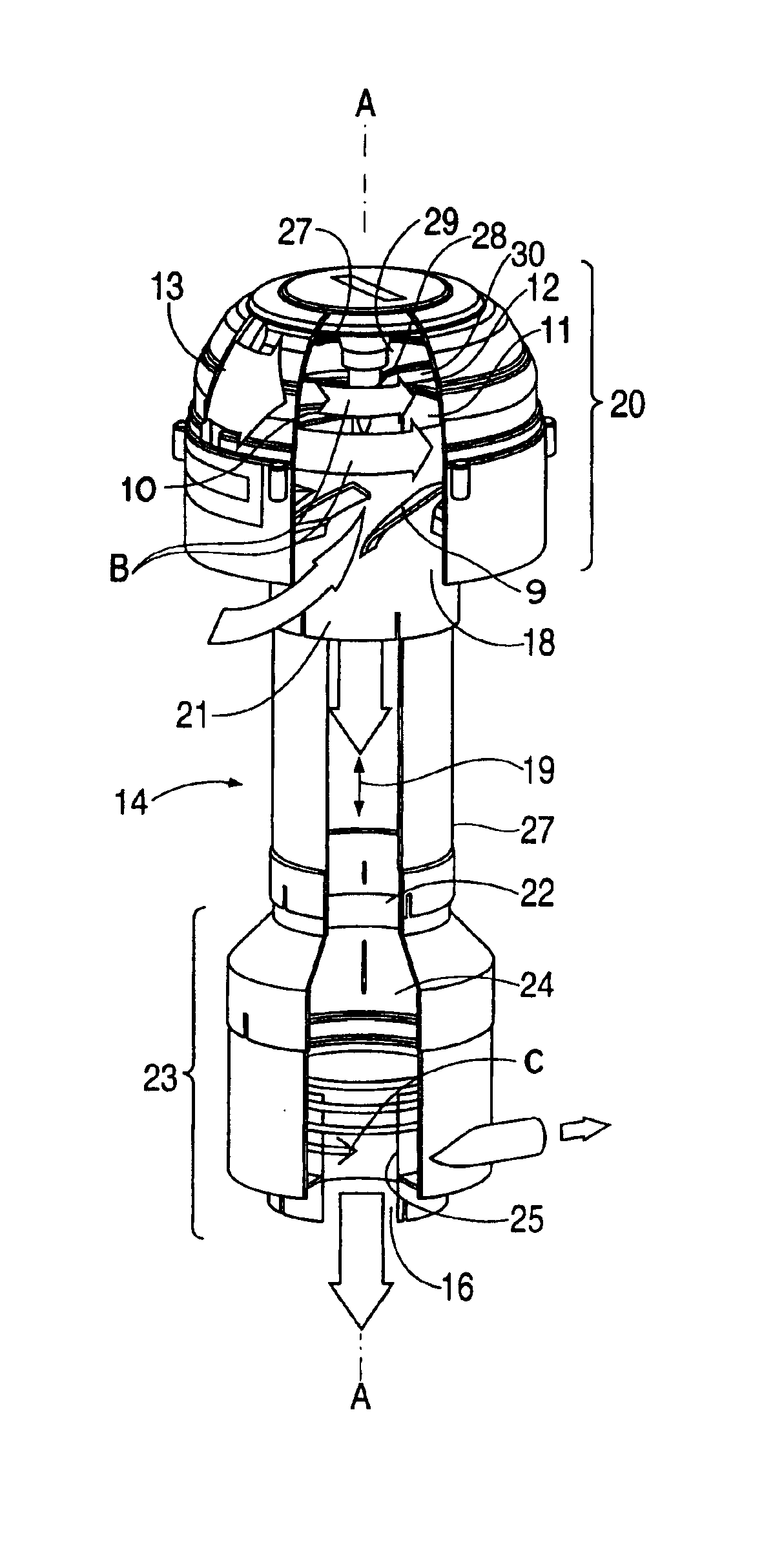
a second stage, scavenger based precleaner in the flow path downstream from the first stage precleaner to centrifugally separate and remove from the vortex flow particles of debris remaining in the vortex flow. This dual stage air precleaner of the invention has been found to increase air filter life under extreme conditions ten times as compared with the use of single stage air precleaners.
centrifugally separating and removing particles of debris from the vortex flow in a separator chamber of a first stage, ejective based precleaner of the system, wherein the centrifugal separating and removing is facilitated by transferring energy from the vortex flow in the flow path downstream of the separator chamber of the first stage precleaner to increase the rotational velocity of the vortex flow in the separator chamber of the first stage precleaner; and

Problems solved by technology

However, it has been found that in extreme conditions, such as found in many landfill and transfer station operations, the known precleaners may fail to provide satisfactory performance.

Method used


Image

  • Air precleaner and method for separating heavier-than-air particulate debris from debris laden air
  • Air precleaner and method for separating heavier-than-air particulate debris from debris laden air
  • Air precleaner and method for separating heavier-than-air particulate debris from debris laden air

Examples


Embodiment Construction

Referring now to the drawings, an air precleaner 14 according to an example embodiment of the invention is shown in FIGS. 3-5. The air precleaner is shown in use on the air intake of an internal combustion engine 2 having an air filter housing 4 on its air intake. An inlet 15 of the air filter housing is connected to a clean air outlet 16 of the air precleaner at the lower end thereof as depicted in FIG. 3. A large prescreen 17, shown in FIG. 3 but not FIG. 4, is located about an inlet 18 of the air precleaner. The prescreen removes the largest contaminants from debris laden air being drawn to the inlet by a vacuum communicated from the engine intake through a flow path 19 extending through the precleaner from the inlet to the outlet. An airflow management structure including fixed vanes 9, is positioned to direct debris laden air drawn into the precleaner through the inlet into a vortex flow in the flow path shown by the arrows at B in FIG. 4.

The air precleaner comprises a first st...


PUM

PropertyMeasurementUnit
Flow rateaaaaaaaaaa
Speedaaaaaaaaaa
Areaaaaaaaaaaa

Abstract

A method and an air precleaner for separating heavier-than-air particulate debris from debris laden air to provide a clean airflow are disclosed. A flow path extends through the precleaner from an inlet to an outlet. Debris laden air is drawn into the inlet by a vacuum in communication with the outlet of the precleaner. A vortex flow of the debris laden air is formed in the flow path and flows through a first stage, ejective based precleaner and a second stage, scavenger based precleaner. Each stage centrifugally separates and removes particles of debris from the vortex flow. Efficient operation under extreme conditions with significant improvement in air filter life, is made possible by the air precleaner and method.

Description

TECHNICAL FIELDThe present invention relates to an improved air precleaner and method for separating heavier-than-air particulate debris from debris laden air which is drawn through the air precleaner for use in apparatus such as an internal combustion engine, a ventilation system, a cooling fan, or an air compressor.BACKGROUND AND SUMMARY OF THE INVENTIONAir precleaners that separate heavier-than-air particles from the air used in combustion type engines are known. One example of a prior art air precleaner, a scavenger based system for a combustion type engine is shown in FIG. 1 wherein air precleaner 1 for combustion type engine 2 comprises an air inlet 3 through which debris-laden-air is drawn from the atmosphere by a vacuum. The vacuum is applied by the intake of the engine which is connected to the outlet of the air precleaner through an air filter housing 4. The air inlet contains fixed vanes for rotating the debris-laden-air drawn into the air precleaner to centrifugally sepa...

Claims


Application Information

Patent Timeline
IPC IPC(8): B01D45/16B01D45/12F02M35/022F02M35/08F02M35/16
CPCB01D45/16F02M35/08F02M35/022F02M35/164
Inventor MOREDOCK, JAMES G.
Owner SY KLONE
Learn More