Horizontal transverse sealing station

a transverse sealing and horizontal technology, applied in the direction of mechanical control devices, process and machine control, instruments, etc., can solve the problems of particularly high transport velocity of film tubes, and achieve the effect of long sealing time, low velocity and high velocity

Active Publication Date: 2016-07-07
SYNTEGON PACKAGING SYST AG
View PDF4 Cites 6 Cited by
  • Summary
  • Abstract
  • Description
  • Claims
  • Application Information

AI Technical Summary

Benefits of technology

[0010]It is proposed that the sealing jaws are mounted on sealing shafts mounted rotatably on the transverse sealing unit. Preferably, two sealing shafts are arranged, in the direction of the weight force, above and below the film tube and respectively support a sealing jaw of a sealing jaw pair or a plurality of sealing jaws of a plurality of sealing jaw pairs. Preferably, the sealing surfaces of the sealing jaws are driven along circular paths, wherein sealing axes of the sealing shafts form centers of the circular paths. The transverse sealing unit can be particularly inexpensive. The sealing jaws can be rotatingly driven at a particularly high velocity. It is possible, in particular for the manufacture of short packs having transverse sealing seams which follow one upon the other at short intervals, for a plurality of sealing jaws of a plurality of sealing jaw pairs to be arranged on the sealing shafts, in particular two to six sealing jaws of two to six sealing jaw pairs. The sealing shafts can rotate at a lower velocity. Preferably, the rotation velocity of the sealing jaws during the contact of the sealing jaws of the jaws with the film tube can be reduced such that the tangential velocity of the sealing surfaces is lower than the transport velocity of the film tube. The displacement movement can compensate this velocity difference. With rotary sealing jaws, a particularly long sealing time can be achieved. Preferably, the rotation velocity at which the sealing jaws are driven between two sealing processes, and the velocity of the displacement movement, are chosen such that a distance between successive transverse sealing seams on the film tube corresponds to a desired pack length. In particular, the rotation velocity between the sealing processes can be increased. This adaptation of the rotation velocity between sealing processes in order to achieve the desired pack length is known to the person skilled in the art as “limping”. Preferably, the limping can be split among the sealing movement and the displacement movement. Acceleration peaks of the drive of the sealing movement and / or of the drive movement can be reduced. Further configurations of a transverse sealing unit which appear sensible to the person skilled in the art are also conceivable. In particular, at least two independent sealing drives can be provided to drive at least two sealing jaw pairs independently of one another. The respectively two sealing jaws of each sealing jaw pair can rotate about two common sealing axes of the sealing jaw pairs. In particular, a plurality of sealing shafts having independent sealing drives can be arranged concentrically to the two sealing axes and respectively support a sealing jaw of the sealing jaw pairs. While one sealing jaw pair performs a sealing process, the further sealing jaw pair or pairs can be driven at a velocity varying from the sealing jaw pair and / or, while one sealing jaw pair is sealing, execute a limping movement. Accelerations necessary for the limping movement can be lower. During the sealing process, the sealing jaws can be braked to a particularly low velocity. Particularly long sealing times can be achieved. Particularly advantageously, the transverse sealing unit can support the sealing jaws on crank mechanisms in a D-shaped sealing movement. During a straight section of the D-shaped sealing movement, the sealing jaws can be moved in the transport direction jointly with the film tube. The sealing surfaces can touch the film tube along a straight section of the sealing movement. Sealing times can be extended further. It is likewise possible for one or more sealing axes of sealing shafts to be mounted displaceably in a direction perpendicular to the transport direction.
[0011]In addition, a horizontal tubular bag machine comprising a horizontal transverse sealing station is proposed. The horizontal tubular bag machine can have particularly long sealing times. A pack quality can be particularly high. Packaging materials which require high sealing times can be processed at high velocity. Alternatively, with the same sealing time, higher velocities can be achieved.

Problems solved by technology

Transport velocities of the film tube can be particularly high.

Method used


Image

  • Horizontal transverse sealing station
  • Horizontal transverse sealing station
  • Horizontal transverse sealing station

Examples


Embodiment Construction

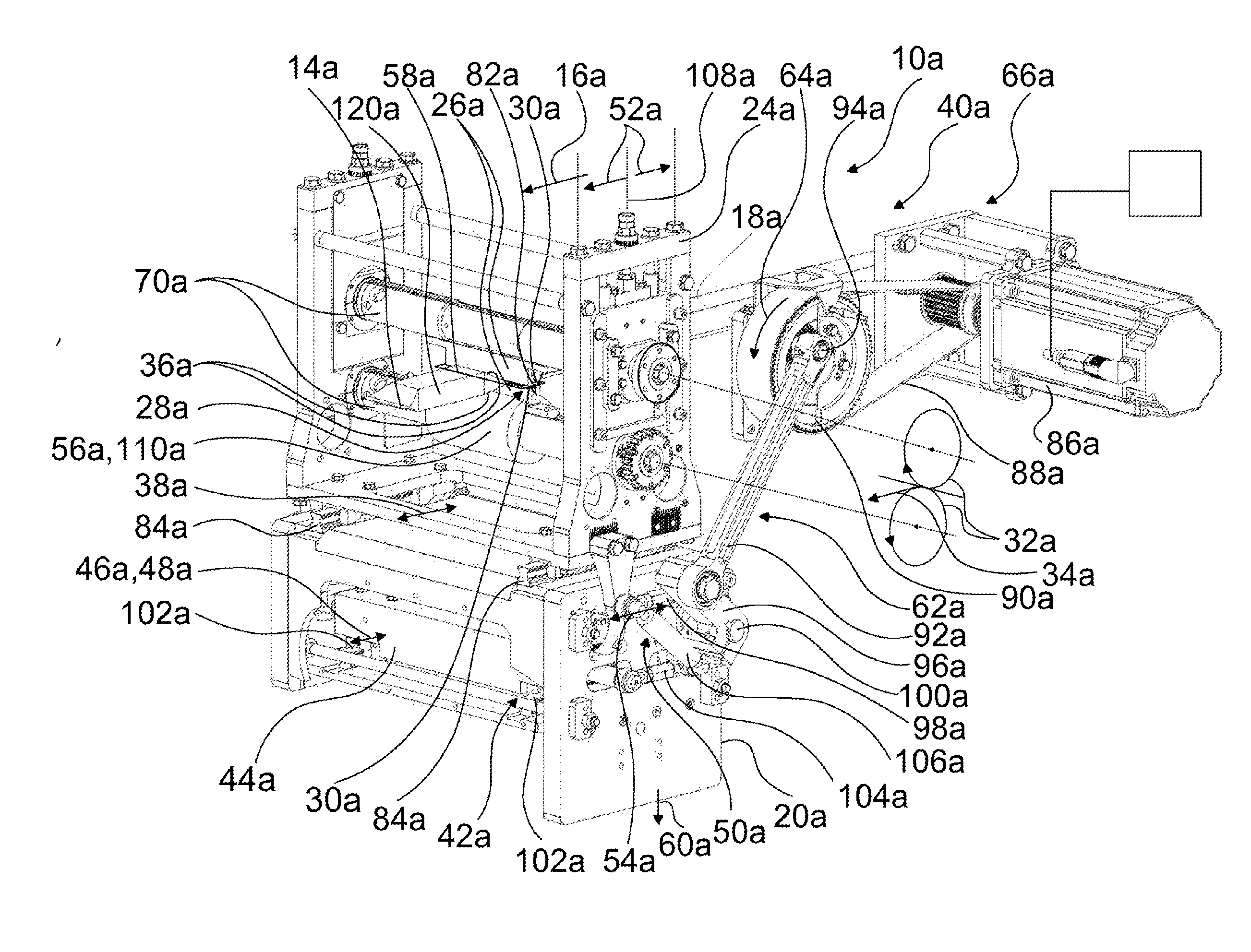
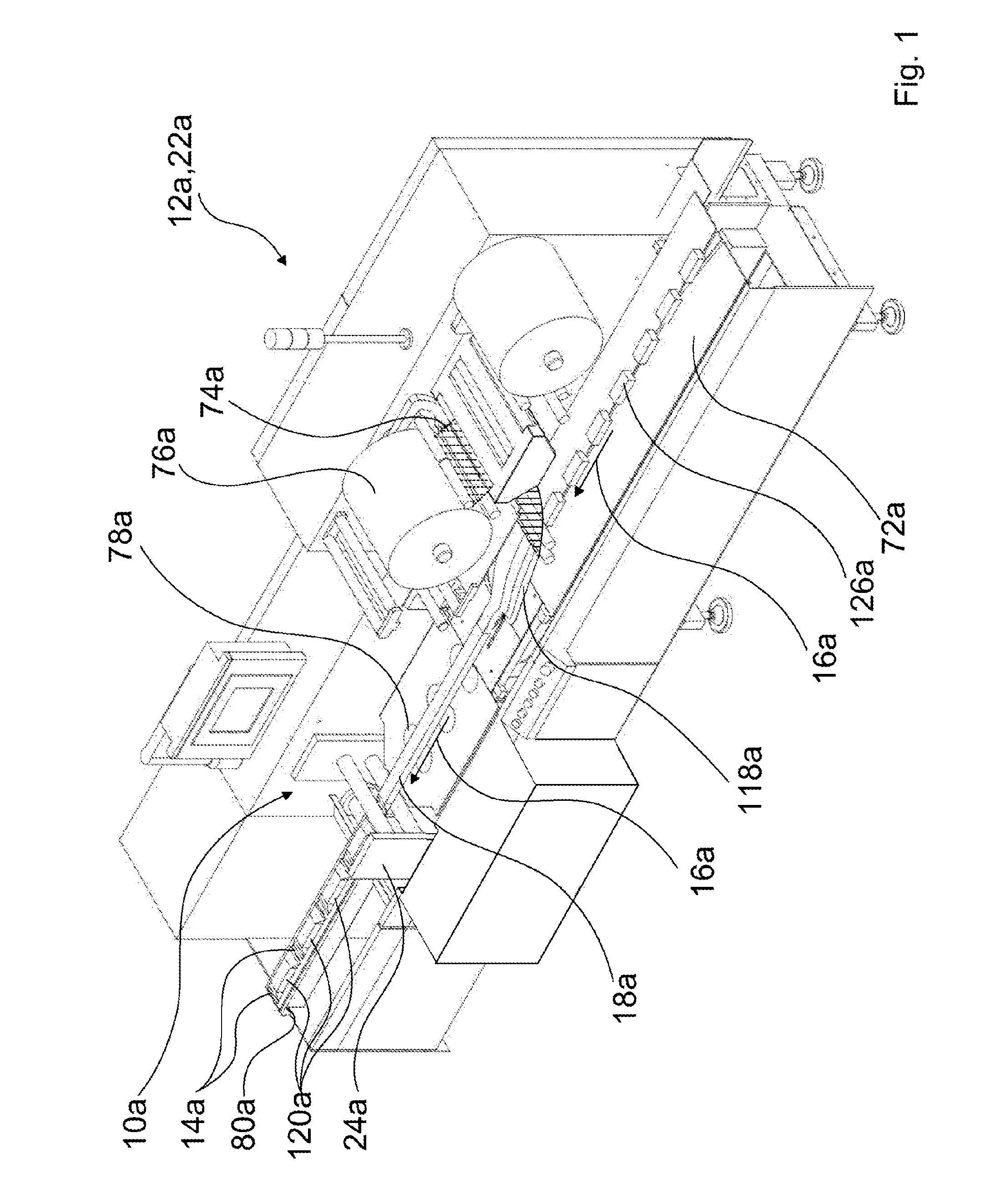
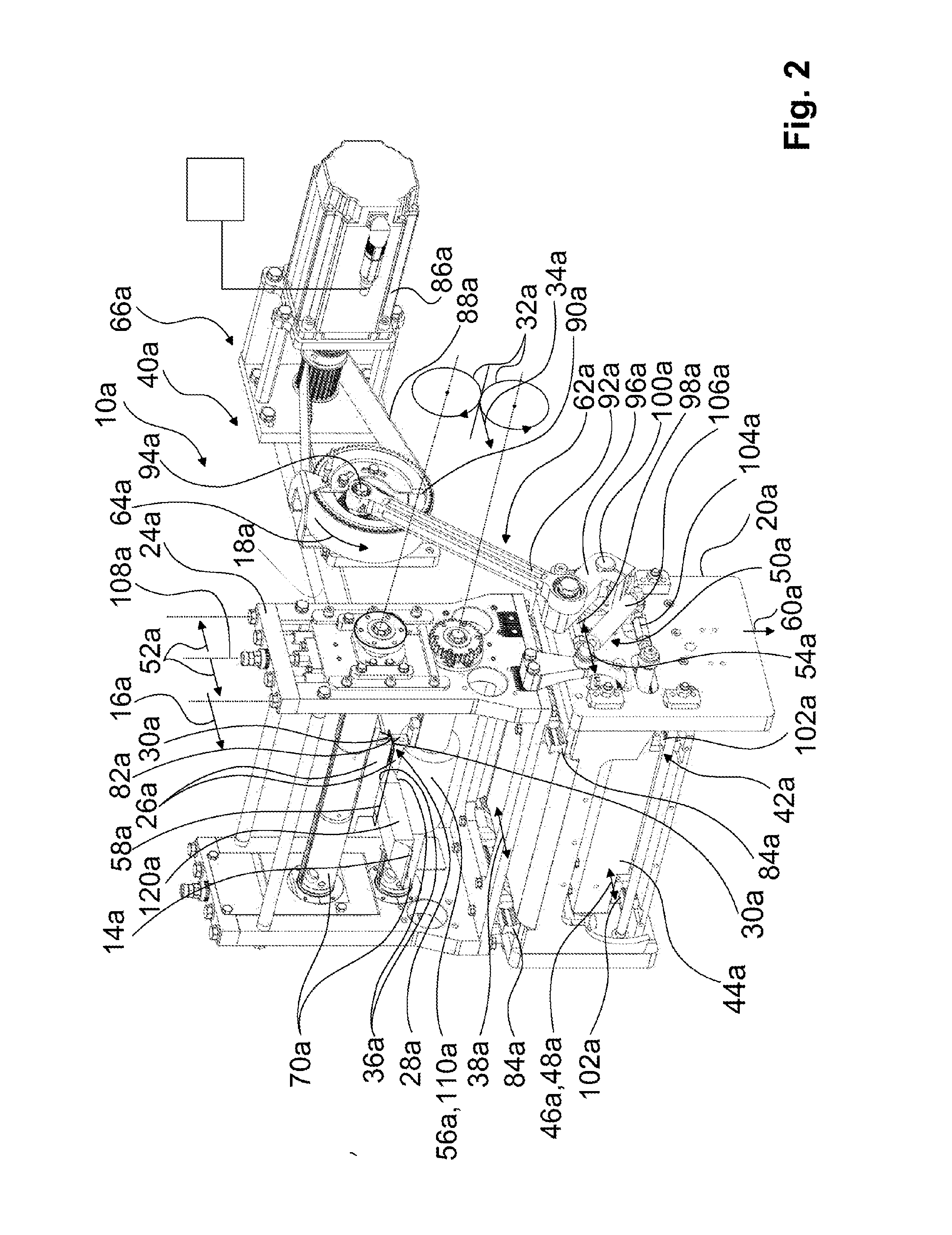
[0017]FIG. 1 shows a packaging machine 22a configured as a horizontal tubular bag machine 12a and comprising a horizontal transverse sealing station 10a. Products to be packed 126a are guided in single track on a feed tray 72a in a horizontal transport direction 16a, by means of dogs (not represented in detail here) of a feed chain, to the horizontal transverse sealing station 10a. A material web 74a is unrolled from a packaging material roller 76a and formed with the aid of a forming shoulder 118a (not indicated here), around the products to be packed 126a, into a film tube 18a. The film tube 18a is transported continuously in the horizontal transport direction 16a and sealed below the products 126a by a horizontal longitudinal sealing unit 78a along a longitudinal sealing seam. Subsequently, the horizontal transverse sealing station 10a seals the film tube 18a along transverse sealing seams 14a and thus forms sealed packs 120a containing the products 126a. The horizontal transvers...


PUM

PropertyMeasurementUnit
movementaaaaaaaaaa
pressureaaaaaaaaaa
displacement movementaaaaaaaaaa

Abstract

The invention relates to a horizontal transverse sealing station (10a-b), in particular for a horizontal tubular bag machine (12a-b), for producing transverse sealing seams (14a-b) on at least one film tube (18a-b) transported in a continuous, at least essentially horizontal transport direction (16a-b), comprising a transverse sealing station base (20a-b) fixedly connected to a packing machine (22a-b), a transverse sealing unit (24a-b), and at least one sealing jaw pair (28a-b) movably mounted on the transverse sealing unit (24a-b) and formed by two sealing jaws (26a-b), the sealing surfaces (30a-b) of which come closer to each other during a sealing process in a sealing movement (32a-b), which relative to the transverse sealing unit (24a-b) is provided with at least one movement component (34a-b) in the transport direction (16a-b), in order to seal material layers (36a-b) of the film tube (18a-b) between the sealing surfaces (30a-b) by way of heating and/or applying pressure, and to remove again at the end of the sealing process. According to the invention the transverse sealing unit (24a-b) is driveably mounted on the transverse sealing station base (20a-b) in a displacement movement (38a-b) that is at least substantially parallel to the transport direction (16a-b).

Description

BACKGROUND OF THE INVENTION[0001]A horizontal transverse sealing station for a horizontal tubular bag machine, for producing transverse sealing seams on at least one film tube transported in a continuous, at least substantially horizontal transport direction, comprising a transverse sealing station base, which is fixedly connected to the tubular bag machine, comprising a transverse sealing unit, and comprising at least one sealing jaw pair, which is movably mounted on the transverse sealing unit and is formed by two sealing jaws and the sealing surfaces of which, during a sealing process, come closer together in a sealing movement having relative to the transverse sealing unit at least one movement component in the transport direction, in order to seal material layers of the film tube between the sealing surfaces, under the application of heat and / or pressure, and to move said material surfaces apart again at the end of the sealing process, has already been proposed.SUMMARY OF THE I...

Claims


Application Information

Patent Timeline
Patent Type & Authority Applications(United States)
IPC IPC(8): B29C65/00B65B51/30B29C65/78B29C65/08B29C65/18B29C65/48
CPCB29C66/849B29C65/18B29C65/4825B29C65/7894B29C65/08B29L2023/00B29C66/4322B29C66/83513B29C66/133B65B51/306B29L2031/7128B29C66/4312B29C65/087B29C65/745B29C66/1122B29C66/81465B29C66/83413B29C66/83543B65B9/067B29C65/305B29C66/723B29C66/8223B29C66/8225B29C66/8246B29C66/8412B29C66/86533B29C66/93451
Inventor THAERIGEN, JAN
Owner SYNTEGON PACKAGING SYST AG
Why Eureka
Try Eureka