
Multi-wheel-driving vehicle

Inactive Publication Date: 2005-04-12
KANZAKI KOKYUKOKI MFG
View PDF20 Cites 37 Cited by
  • Summary
  • Abstract
  • Description
  • Claims
  • Application Information

AI Technical Summary

Benefits of technology

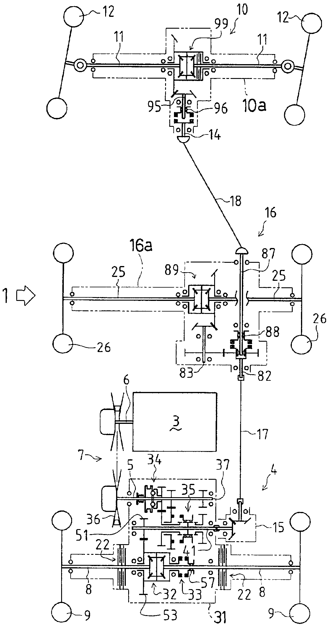
A first object of the present invention is to provide a multi-wheel-driving vehicle including three or more axles arranged in parallel along a longitudinal axis of the vehicle. Each of the axles is provided on each end thereof with a respective drive wheel. One of the three or more axles is a steering axle provided with steerable drive wheels, and includes power dividing means for permitting rotary speed among the axles, wherein the steering axle is drivingly differentially connected with the other axles so that the steerable drive wheels can be driven while receiving nicely distributed power.
To achieve the first object, the vehicle is provided with a pair of transmission members like coaxial shafts between which a first power dividing means, such as a one-way clutch, is interposed. The steering axle synchronously interlocks with one of the transmission members, and at least another axle, preferably, all the axles other than the steering axle interlock with the other transmission member. Power is transmitted through the first power dividing means between both the transmission members while the first power dividing means allows a difference of rotary speed between the transmission members.
A second object of the present invention is to provide the multi-wheel-driving vehicle as mentioned above with a braking force, supplied by fewer brakes, that is effectively transmitted to all drive wheels of a vehicle in response to a simple braking operation by a driver, thereby enhancing braking effectiveness and reducing the cost of providing brakes.

Problems solved by technology

However, in such a cited conventional power distribution structure, the frontmost axle for steerable front drive wheels is drivingly synchronized with the rearmost axle for unsteerable rear drive wheels, so that the driving of the front wheels is restricted while turning by the driving of the rear wheels, thereby hindering a smooth steering of the vehicle.
Furthermore, this cited document does not disclose an arrangement of brakes.
However, the braking force is not effectively transmitted to the middle axle interlocking with the second transmission shaft.
If only one of the halves is provided thereon with a brake, the braking force cannot be effectively transmitted to the other half.

Method used


Image

  • Multi-wheel-driving vehicle
  • Multi-wheel-driving vehicle
  • Multi-wheel-driving vehicle

Examples


second embodiment

Description will now be given on various driving transmission systems as modifications of the above-mentioned first preferred embodiment. Referring to a second embodiment shown in FIG. 9, instead of one-way clutch 20, a center differential 23 is interposed between input shaft 82 and second PTO shaft 87 in middle transaxle device 16 for sharing the torque transmitted from rear transaxle device 4 between front transaxle device 10 and middle transaxle device 16, thereby permitting a difference in rotary speed between front wheels 12 and middle wheels 26. Center differential 23 differentially connects both shafts 82 and 87 with each other. Input shaft 82 is inserted into a differential casing 23a of center differential 23 so as to make differential casing 23a integrally rotatable with input shaft 82. In differential casing 23a are disposed a pair of differential side gears 23b and 23c and a pair of differential pinions 23d. Differential side gear 23b is rotatably provided around input s...

third embodiment

The third embodiment employs a control system for operation of the front clutch and differential-locking of main-axle-differential 32 and center differential 23 as shown in FIG. 11, wherein the front clutch are engaged and main-axle-differential 32 and center differential 23 are differentially locked so as to effectively transmit the braking force generated by single brake 22 in rear transaxle device 4 to middle and front transaxle devices 16 and 10.

Beside the driver's seat of vehicle 1 are provided a center differential locking lever 121′ replacing center clutch lever 121, and a main-axle-differential locking lever 125. Each of differential locking levers 121′ and 125 is shiftable between its locking position and its unlocking position. A switching sensor 49′ is provided so as to be switched on when center differential locking lever 121′ is located at its locking position. A switching sensor 65 is provided so as to be switched on when main-axle-differential locking lever 125 is loc...

first embodiment

Further, the controlling parts for main-axle-differential locking mechanism 33 such as main-axle-differential locking lever 125, hydraulic cylinders 123 and solenoid valve 124 are also provided in the control system of the first embodiment shown in FIG. 8. These features are omitted in FIG. 8 because they are irrelevant to the description of the clutch-controlling for effectively transmitting braking force to all wheels 9, 26 and 12 of vehicle 1.

In the third embodiment, the forced controlling of main-axle-differential locking mechanism 33 is required for transmitting the braking force of only one brake 22 to both rear axles 8. Therefore, in this embodiment, when brake pedal 19 is depressed, solenoid valves 114, 115 and 124 are controlled by controller 30 so as to forceably locate main-axle-differential locking slider 57, center differential locking clutch slider 88′ and front clutch slider 96 at their locking or clutch-on positions. Thus, the braking force generated by only one brak...


PUM


Abstract

A multi-wheel-driving vehicle including at least three parallel axles each of which is provided on both ends thereof with respective drive wheels and including power dividing means for permitting the rotary speed among the axles, is improved in its effect of braking so that the braking force of fewer brakes is effectively transmitted to all drive wheels of a vehicle according to a simple braking operation by a driver. The power dividing means, for example, a differential gear unit, includes an input member and a pair of output members, like differential side gears, each of which interlocks with at least one of the axles so as to differentially share a driving force received by the input member between the pair of output members. The multi-wheel-driving vehicle comprises a brake provided on one of the at least three axles, and locking means for locking the input member and the pair of output members together, so that when a driver operates a brake-operating tool for braking, the locking means is automatically operated to lock the input member and the pair of output members together.

Description

CROSS-REFERENCE TO RELATED APPLICATIONSNot applicableSTATEMENT REGARDING FEDERALLY-SPONSORED RESEARCH AND DEVELOPMENTNot applicableREFERENCE TO MICROFICHE APPENDIX / SEQUENCE LISTING / TABLE / COMPUTER PROGRAM LISTING APPENDIX(Submitted on a Compact Disc and an Incorporation-by-reference of the Material on the Compact Disc)Not applicable.BACKGROUND OF THE INVENTION1. Field of the InventionThe present invention relates to a multi-wheel-driving vehicle provided with not less than six drive wheels. More particularly, the present invention relates to a technique for improving the braking capacity of the multi-wheel-driving vehicle, as well as compactness and cost savings in its construction.2. Background ArtConventionally, there is a multi-wheel-driving vehicle having three or more axles disposed in parallel, each of which is provided at its left and right ends with respective drive wheels. Generally, each axle is divided into left and right halves which are differentially connected with each...

Claims


Application Information

Patent Timeline
IPC IPC(8): B60K17/34F16D55/40F16D55/24B60K23/08B60K17/36
CPCF16D55/40B60K17/34
Inventor HASEGAWA, TOSHIYUKI
Owner KANZAKI KOKYUKOKI MFG
Learn More