Buoyant hand tool
a hand tool and buoyant technology, applied in the field of buoyant hand tools, can solve the problems of substantial damage, drop of hand tools irretrievably into the water, and detrimental corrosion, and achieve the effect of buoyancy in water, low density, and high buoyancy
- Summary
- Abstract
- Description
- Claims
- Application Information
AI Technical Summary
Benefits of technology
Problems solved by technology
Method used
Image

Examples
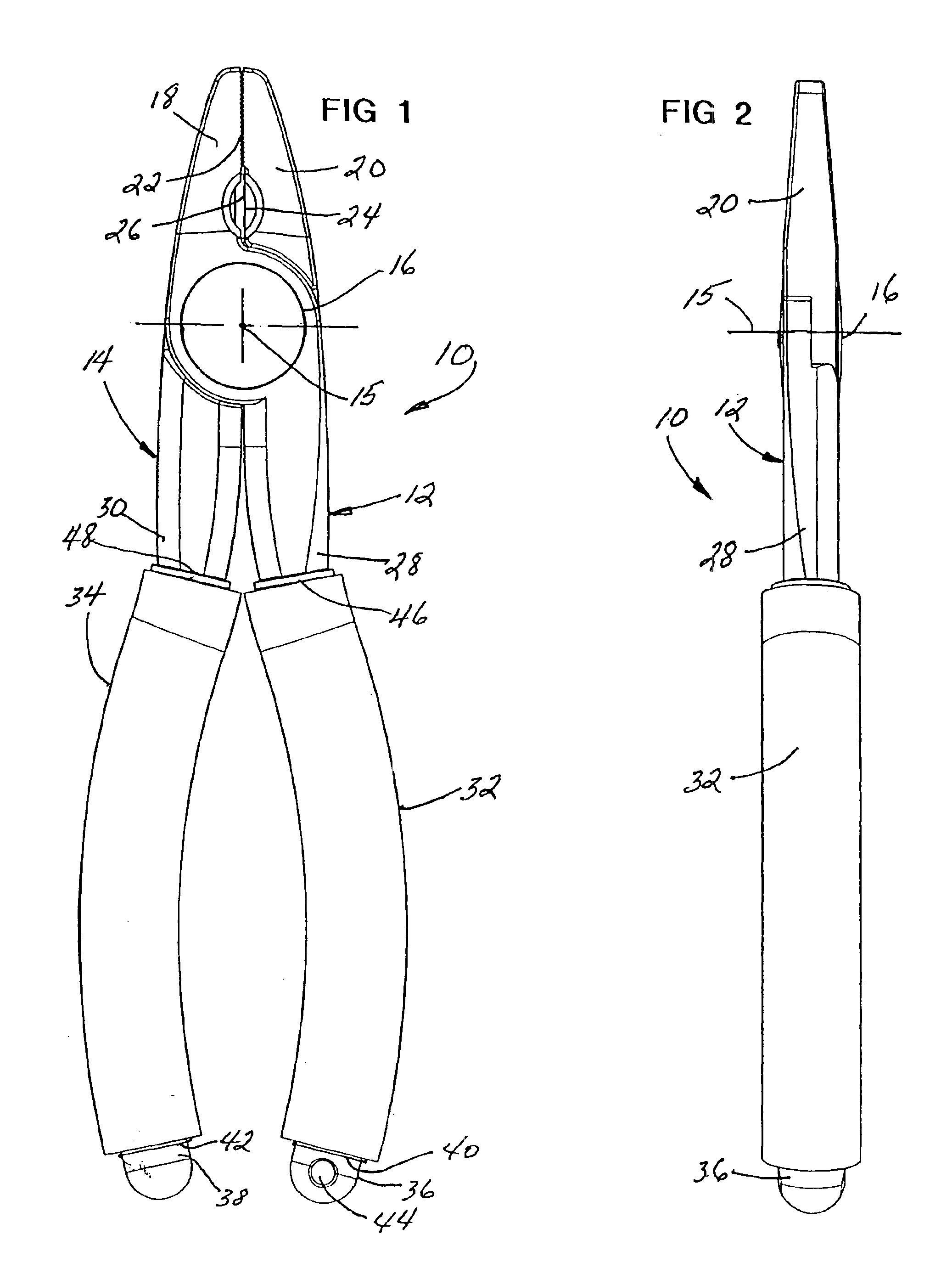
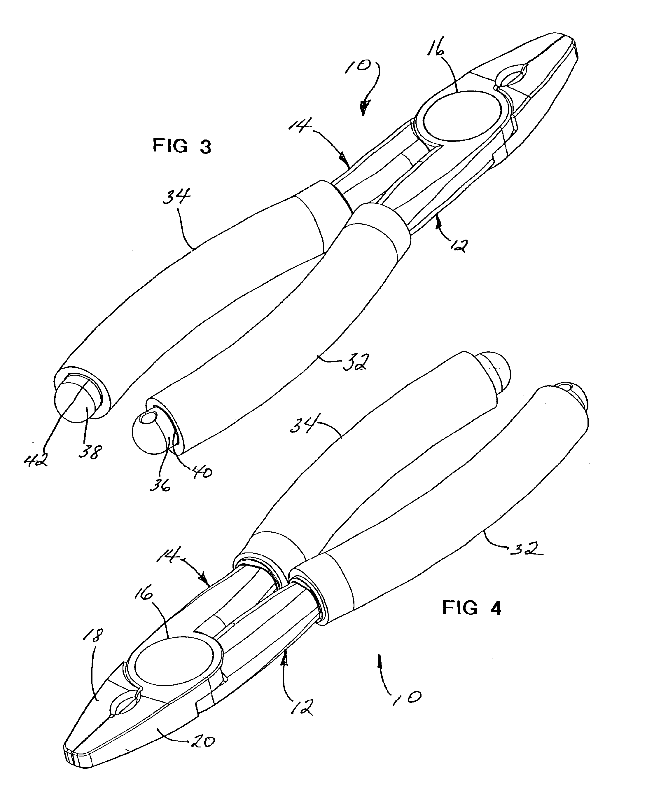
embodiment 10
Referring now to the drawings, and particularly to FIGS. 1 to 4, one embodiment of the invention is there shown generally at numeral 10. This embodiment 10 is in the form of a pair of pliers having elongated handle portions 28 and 30 and shorter jaw portions 18 and 20, each forming respective end portions of lever members 12 and 14, respectively.
The two lever members 12 and 14 are pivotally connected together at their central overlapping portions about a pivotal axis 15. A retaining cap 16, described herebelow secures the two lever members 12 and 14 together. These components are formed of molded plastic or fiberglass material generally, and are preferably formed of a 43% glass fiber reinforced NYLON produced by Polyplastics Celanese, Nylon PA-66, Material No. 1603-2 having a relatively low density of 1.47 g / cc. The mating facing surfaces 22 of each of the jaw portions 18 and 20, respectively, are serrated or grooved for enhanced gripping of objects therebetween when the handle port...
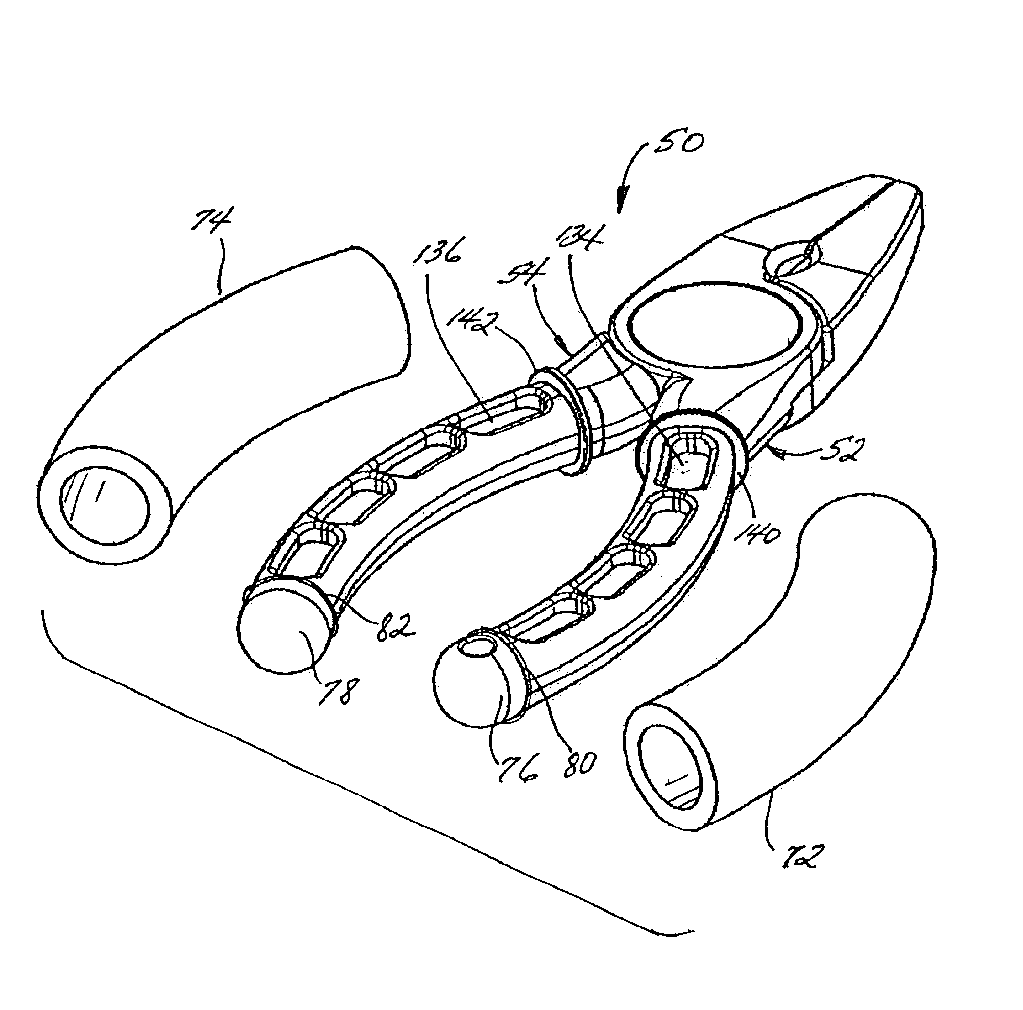
embodiment 50
Another embodiment of the invention is shown generally at numeral 50 in FIGS. 5 to 8. This embodiment 50 is of a shorter, stubbier nature in proportion; however, construction is very similar to that above described in FIGS. 1 to 4. Each of the lever members 52 and 54 include jaw portions 58 and 60 which come together at mating serrated surfaces 62 for gripping objects therebetween. A cutting blade 64 bearing against flat surface 66 functions as previously described to cut objects. Pivotal engagement about the central pivot axis 55 is secured by retaining cap 56.
Foam low-density sheaths 72 and 74 have been slidably engaged over the handle portions 68 and 70 of each corresponding lever member 52 and 54, respectively. Flanges 80, 82, 140 and 142 prevent axial or longitudinal movement of each of the foam sheaths 72 and 74 during use.
The material selections used to mold each of the lever members 52 and 54 is as above described while the foam sheaths 72 and 64 are similarly constructed as...
embodiment 150
As previously described, buoyancy in water of this embodiment 150 is accomplished by the combination of the lighter-than-water density of the sheath 154, in combination with a plurality of cavities 158 which are molded from either side of the handle portion 156 thereinto. The cavities 158 each have a depth which approaches a central plane or web of the handle portion 156, laterally opening outwardly as shown in FIG. 26.
These cavities 158 are formed in open fashion such that, when the tightly fitting tubular sheath 154, formed of the above-described somewhat elastic foam material, is slidably assembled onto the handle portion 156 as shown in FIG. 26, an airtight seal of each of the cavities 158 is achieved. The lighter-than-water density of the sheath 154, in combination with the total airtight volume determined by design of the collective sealed cavities 158, renders this embodiment 150 buoyant, with the handle assembly 152 being the uppermost floating portion at or slightly above t...
PUM
 Abstract
Description
Claims
Application Information
 - R&D
- Intellectual Property
- Life Sciences
- Materials
- Tech Scout
- Unparalleled Data Quality
- Higher Quality Content
- 60% Fewer Hallucinations
Browse by: Latest US Patents, China's latest patents, Technical Efficacy Thesaurus, Application Domain, Technology Topic, Popular Technical Reports.
© 2025 PatSnap. All rights reserved.Legal|Privacy policy|Modern Slavery Act Transparency Statement|Sitemap|About US| Contact US: help@patsnap.com