
Microphone for hearing aid and communications applications having switchable polar and frequency response characteristics

a technology of frequency response and microphone, which is applied in the direction of frequency response correction, piezoelectric/electrostrictive transducer, transducer type, etc., can solve the problems of acoustically complex killion reference, inability to independently choose the frequency response of the microphone in the directional and omni-directional modes, and prior art killion reference is acoustically complex and consequently difficult to implement. , to achieve the effect of reducing environmental

Inactive Publication Date: 2005-04-05
ETYMOTIC RES
View PDF11 Cites 31 Cited by
  • Summary
  • Abstract
  • Description
  • Claims
  • Application Information

AI Technical Summary

Benefits of technology

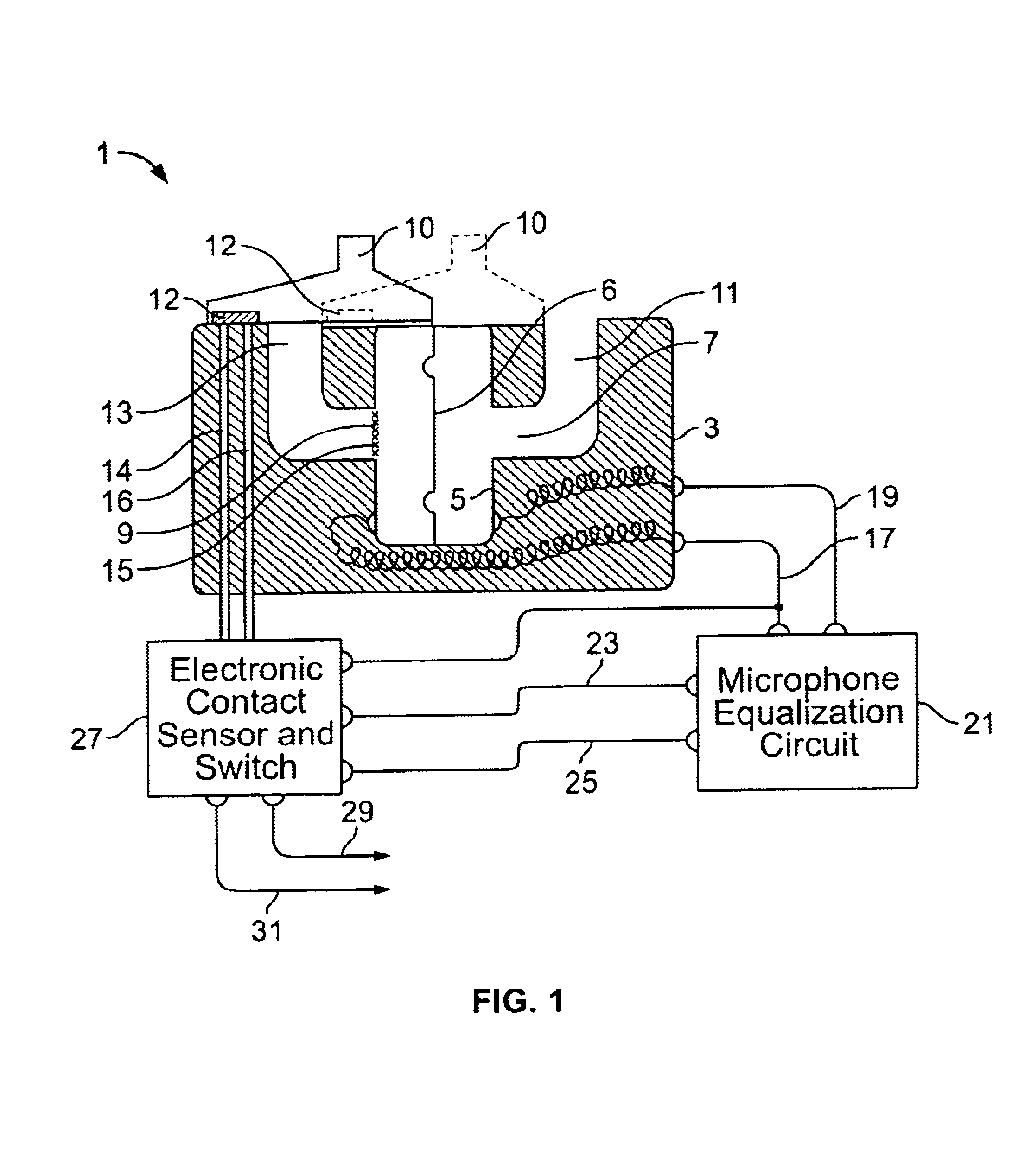
Depending on the mode selected by the user, circuitry of the assembly selects a given output from the microphone. More specifically, the circuitry, which may be wholly or partially integrated into the microphone cartridge or an assembly housing, senses the position of the actuator switch, i.e., whether the rear inlet tube is plugged or unplugged, and selects an output that is desirable based on the operative mode. For example, if the rear inlet tube is unplugged, indicating the directional mode, the circuitry may select an equalized output from the microphone, or one with lower gain, or one including greater environmental noise reduction, for example. If, on the other hand, the rear inlet tube is plugged, indicating the omni-directional mode, the circuitry may select a non-equalized output from the microphone, or one with higher gain, or one including less environmental noise reduction, for example. In any case, the circuitry senses the mode selected and dictates the output from the microphone correspondingly.

Problems solved by technology

However, such other prior art hearing aids, which can be used either as directional or omni-directional devices, have the marked disadvantage that when the aid is used as a omni-directional aid, it will have a given response characteristic relative to frequency, and when the aid is used as a directional aid, it will have an entirely different response characteristic relative to frequency.
The prior art Killion reference, however, did not provide flexibility in independently choosing the resulting frequency response of the microphone in the directional and omni-directional modes.
In addition, the prior art Killion reference was acoustically complex and consequently difficult to implement.

Method used


Image

  • Microphone for hearing aid and communications applications having switchable polar and frequency response characteristics
  • Microphone for hearing aid and communications applications having switchable polar and frequency response characteristics
  • Microphone for hearing aid and communications applications having switchable polar and frequency response characteristics

Examples


Embodiment Construction

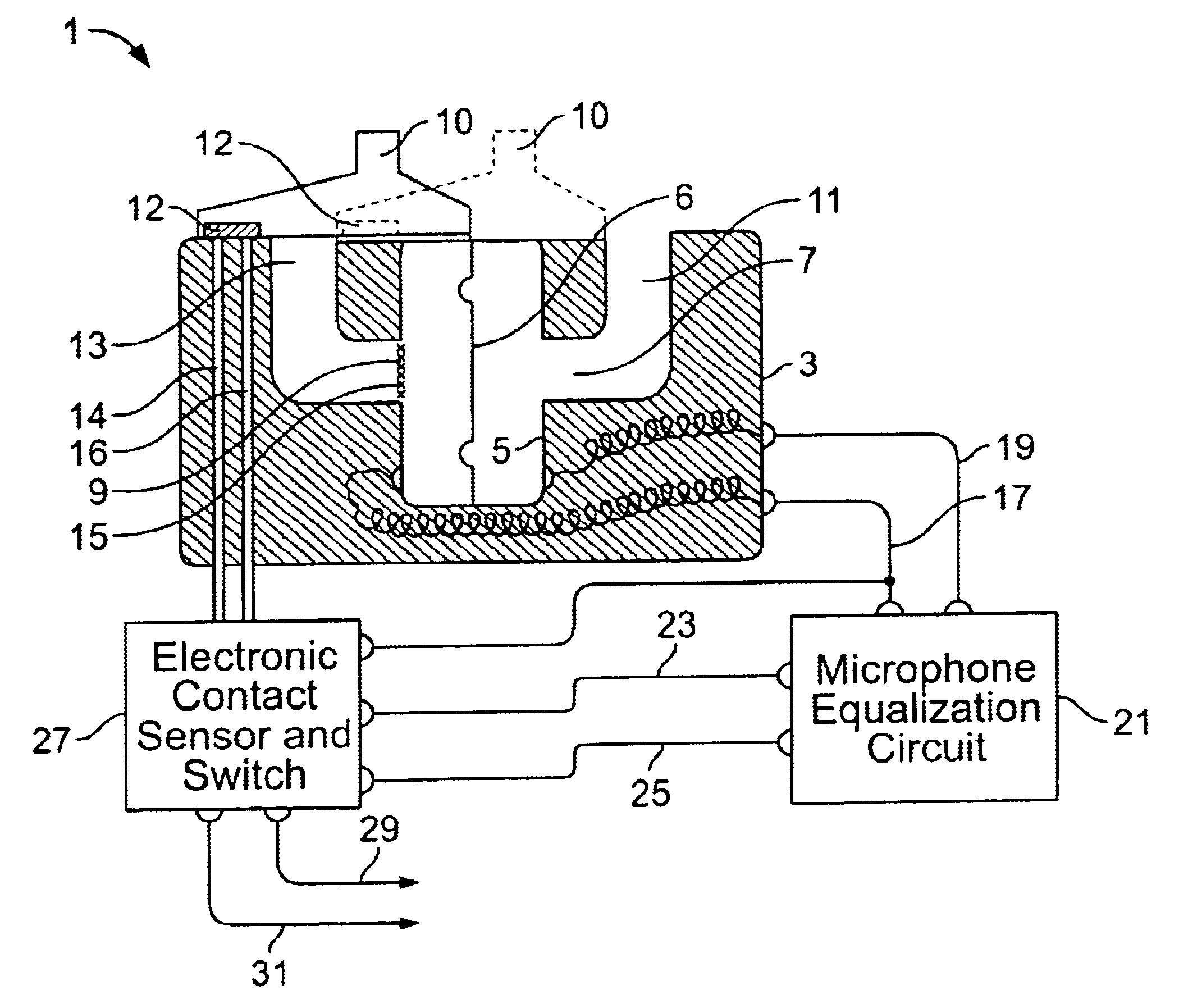
FIG. 1 illustrates one embodiment of a microphone assembly according to the present invention. Microphone assembly 1 comprises a microphone housing 3 that encloses a microphone cartridge 5 therein. Microphone cartridge 5 has a diaphragm 6, a front sound inlet port or opening 7 and a rear sound inlet port or opening 9. Front sound inlet port 7 and rear sound inlet port 9 engage front sound inlet tube 11 and rear sound inlet tube 13, respectively, of microphone housing 3. An acoustic resistor 15 is located in rear sound inlet port 9. Acoustic resistor 15, however, may instead be located in rear sound inlet tube 13.

Microphone assembly 1 further comprises an actuator switch 10 that modifies the directional characteristics of the microphone assembly 1. Specifically, when the actuator switch 10 is in a directional position represented by the dotted lines in FIG. 1, the rear sound inlet tube 13 is uncovered and the microphone assembly 1 acts as a directional microphone. When the actuator s...


PUM


Abstract

A microphone assembly generally for hearing aid and communications applications is disclosed. The microphone assembly operates in both directional and non-directional or omni-directional modes. The microphone assembly has front and rear sound inlet tubes, and an actuator switch that may be moved between a first position in which the rear tube is plugged, defining the omni-directional mode, and a second position in which the rear tube is unplugged, defining the directional mode. Circuitry senses the position of the actuator switch and selects a microphone output based on the position sensed.

Description

BACKGROUND OF THE INVENTIONVarious types of hearing aids are known which have non-directional or omni-directional response characteristics; and, other types of hearing aids are known which have directional response characteristics. Still other prior art hearing aids are known which can be utilized either as directional hearing aids or as omni-directional hearing aids by suitable modification of the structure. However, such other prior art hearing aids, which can be used either as directional or omni-directional devices, have the marked disadvantage that when the aid is used as a omni-directional aid, it will have a given response characteristic relative to frequency, and when the aid is used as a directional aid, it will have an entirely different response characteristic relative to frequency. For example, curve or response line A of FIG. 3 in prior art U.S. Pat. No. 3,835,263 (Killion) shows a typical response of an omni-directional device wherein the lower frequency portion of the...

Claims


Application Information

Patent Timeline
Patent Type & Authority Patents(United States)
IPC IPC(8): H04R25/00H04R3/04
CPCH04R25/43H04R25/402H04R3/04
Inventor KILLION, MEAD C.SCHULEIN, ROBERT B.CARLSON, ELMER V.DRAMBAREAN, VIOREL
Owner ETYMOTIC RES
Learn More