
Method and apparatus for reproducible sample injection on microfabricated devices

a microfabricated device and reproducible technology, applied in the field of miniature instruments, can solve the problems of large sampling volume, time-consuming and expensive existing dna analysis procedures, and the use of capillary electrophoresis techniques in seemingly limitless applications in both industry and academia, and achieve the effect of improving the reproducibility of the sample volume injected into the reaction channel and small fixed-volume sample injection

Inactive Publication Date: 2005-04-05
MICROCHEM SOLUTIONS
View PDF28 Cites 75 Cited by
  • Summary
  • Abstract
  • Description
  • Claims
  • Application Information

AI Technical Summary

Benefits of technology

This approach achieves precise and reproducible small-volume sample injection, overcoming the limitations of prior methods by ensuring consistent analyte delivery and reducing dispersion, thereby enhancing the reliability of microfluidic systems for chemical analysis and separation techniques.

Problems solved by technology

Yet due to the complexity of the equipment that detects and measures DNA samples and the difficulty in preparing the samples, the existing DNA analysis procedures are often time-consuming and expensive.
Capillary electrophoresis techniques are employed in seemingly limitless applications in both industry and academia.
The limitation of this method is the large sampling volume.
This volume is too large to be used for high-resolution separations.
Later, an internal loop injection valve with an injection loop volume of ≧20 nL has become commercially available, but connecting capillaries to this valve is too much of a challenge and consequently it is not often used in capillary electrophoresis.
It is also difficult to maintain consistency in injecting a fixed volume of sample by either of these techniques, as the sample volume injected are susceptible to changes in sample viscosity, temperature, etc., thereby resulting in relatively poor reproducibility in injected sample volumes between separation runs.
Electromigration additionally suffers from electrophoretic mobility-based bias.
Often, the readlength of DNA sequencing is limited by the low signal intensity rather than the resolution for the long fragments.
This degrades the resolving power and makes the separation irreproducible.
Double-T injectors also suffer from dispersion of analytes into the separation channel.
However, when samples of different ionic strength and viscosity are to be analyzed, that calibrated potential balance for the device is no longer applicable, and consequently giving rise to undesired and / or irreproducible results.
On the other hand, a considerable increase in the steady-state concentration will occur at the sample / gel interface for the large fragments because of their reduced mobility in the gel.
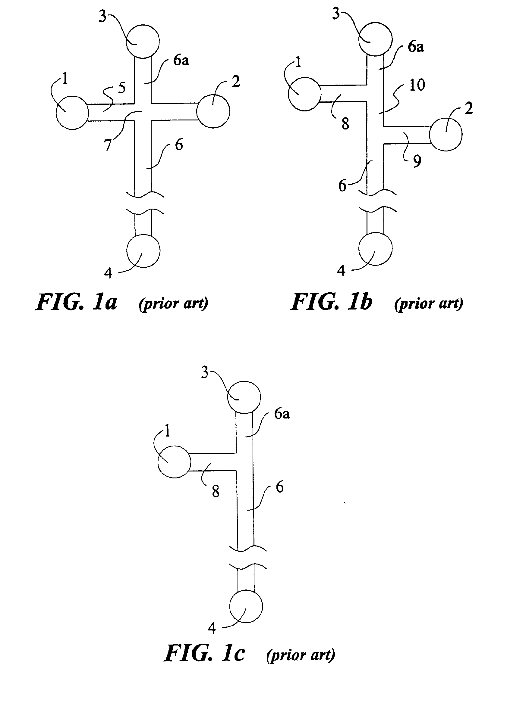
However, there are two major problems associated with the T-injector.
The first problem is the augmented electrophoretic mobility-based bias.
The second problem is the difficulty in precisely controlling a finite amount of analytes into the separation-channel 6.
This problem is associated with the variation of length of the half “cross-channel”8.
The reservoirs are holes drilled or physically attached and their positions and dimensions cannot be reproducibly and precisely produced.
Variation of the length of this channel makes the problem even more challenging.

Method used


Image

  • Method and apparatus for reproducible sample injection on microfabricated devices
  • Method and apparatus for reproducible sample injection on microfabricated devices
  • Method and apparatus for reproducible sample injection on microfabricated devices

Examples


Embodiment Construction

The present description is of the best presently contemplated mode of carrying out the invention. This description is made for the purpose of illustrating the general principles of the invention and should not be taken in a limiting sense. The scope of the invention is best determined by reference to the appended claims.

For purpose of illustrating the principles of the present invention and not limitation, the present invention is described by reference to embodiments directed to separation in capillary electrophoresis. The present invention is equally applicable to chemical reactions, diagnostics and / or analysis in microfluidic devices. All references to separation channel hereinafter are examples of reaction channels, and are equally applicable to channels for other purposes in microfluidic devices.

Microfabricated electrophoresis chips possess many unique advantages over conventional capillary electrophoresis. One of them is the so-called “differential concentration” effect for se...


PUM

PropertyMeasurementUnit
internal diameteraaaaaaaaaa
volumesaaaaaaaaaa
volumeaaaaaaaaaa

Abstract

Fixed volumes of samples are metered into the reaction channel of a microfluidic device using one or more slidable blocks having at least one fixed-length sample metering channel. In another aspect of the present invention, fixed volumes of samples are metered into the reaction channel using one or more slidable blocks having at least one fixed-length sample metering channel. In another aspect of the present invention, a sample injection scheme based on injection time is implemented using relatively sliding blocks of separation channels and sample channels. In a further aspect of the present invention, separation channels are configured in relation to the slidable block in a manner that enables separations to be conducted continuously for high-throughput assays.

Description

BACKGROUND OF THE INVENTION1. Cross-ReferenceU.S. patent application Ser. No. 10 / 076,042 entitled METHOD AND APPARATUS FOR SAMPLE INJECTION ON MICROFABRICATED DEVICES, concurrently filed on Feb. 11, 2002, which is assigned to MicroChem Solutions, Inc., the assignee of the present invention, and which is fully incorporated by reference herein.2. Field of the InventionThe present invention relates generally to miniature instrumentation for conducting chemical reaction and / or bio-separation, and diagnostics and / or analysis related thereto, and more particularly, to the introduction of samples to the chemical reaction and / or bio-separation channels in microfabricated devices.3. Description of Related ArtBioanalysis, such as DNA analysis, is rapidly making the transition from a purely scientific quest for accuracy to a routine procedure with increased, proven dependability. Medical researchers, pharmacologists, and forensic investigators all use DNA analysis in the pursuit of their tasks...

Claims


Application Information

Patent Timeline
Patent Type & Authority Patents(United States)
IPC IPC(8): B01D61/24B01D61/42B01D61/28B01L3/00B01L3/02B01D61/56B81B1/00G01N27/447G01N1/00G01N35/10G01N1/34B01L99/00G01N35/00
CPCB01D61/28B01L3/0241B01L3/0293B01L3/502738B01L3/502746B81B1/004G01N27/44743G01N27/44791G01N35/10G01N35/1016B01D61/56Y10T436/25375B01L3/5025B01L2200/027B01L2200/0605B01L2300/0816B01L2400/0415B01L2400/0421B01L2400/0487B01L2400/0622B01L2400/065B81B2201/058G01N2001/4016G01N2030/204G01N2035/00158G01N2035/00247G01N2035/1032Y10T436/255Y10T436/25Y10T436/11Y10T436/2575
Inventor LIU, SHAORONGLU, JUAN
Owner MICROCHEM SOLUTIONS
Learn More