
Syringe system

a syringe and system technology, applied in the field of syringe systems, can solve the problems of limiting the widespread use of transendomyocardial injection, cell migration and division, and major issue limiting angiogenesis, and achieve the effects of small injection volume, convenient control, and small volum

Inactive Publication Date: 2005-09-08
SCHWARTZ ROBERT S +2
View PDF29 Cites 130 Cited by
  • Summary
  • Abstract
  • Description
  • Claims
  • Application Information

AI Technical Summary

Benefits of technology

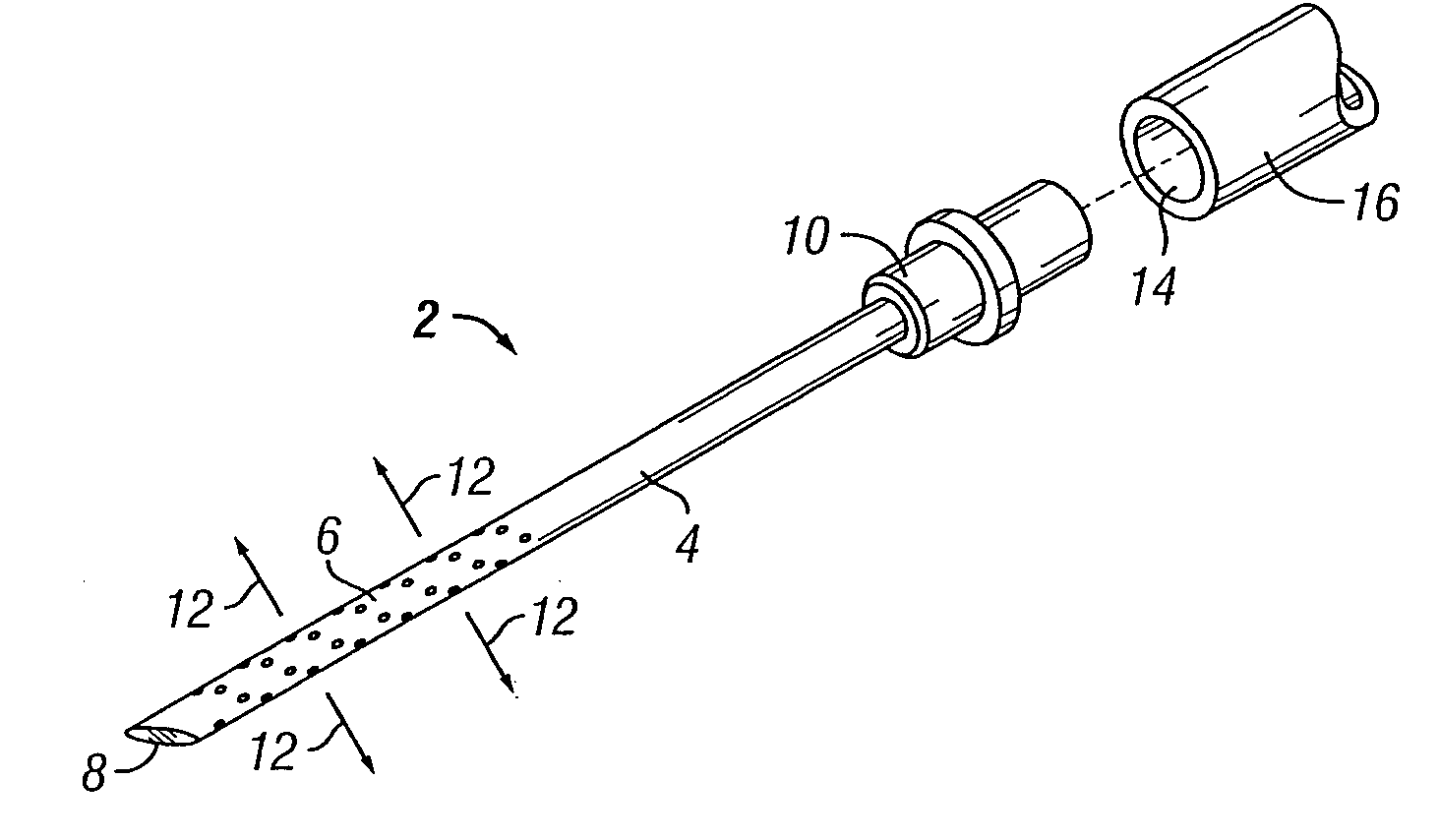
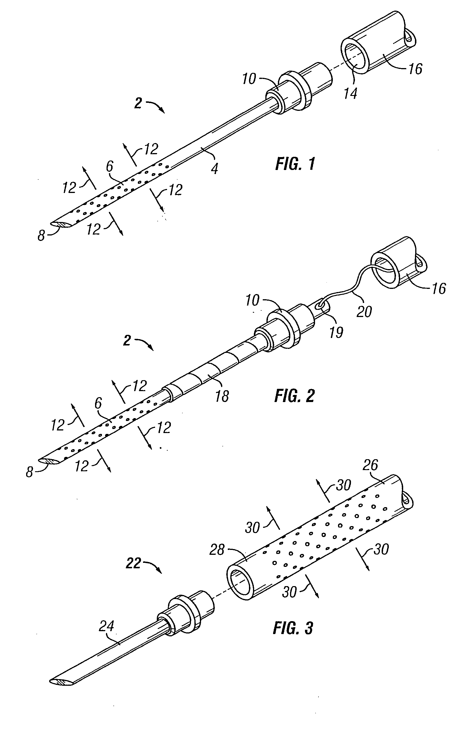
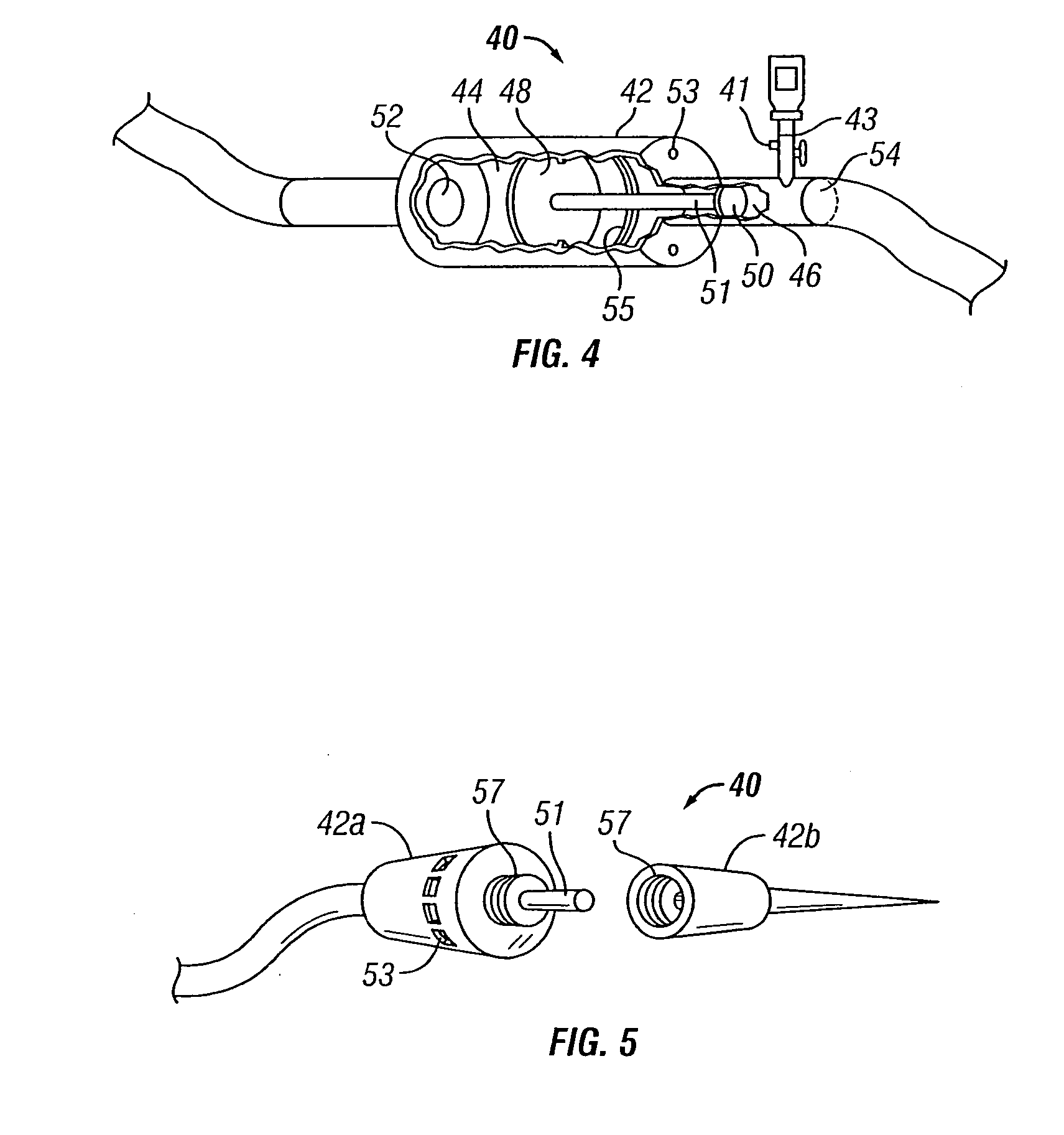
[0016] Generally, the present invention overcomes many of the problems in the art by providing a medical device capable of creating a cloud of injectate, in tissue, having a predetermined shape, size and concentration. The device includes a needle system having at least one elongate member with a plurality of holes constructed and arranged to create the desired cloud shape when injectate is forced therethrough. Preferably two elongate, telescopically related members act together to create a desired cloud shape. There is also a provision for an in-line hydraulic reducer assembly which allows an easily controlled, relatively large volume of liquid to be used to provide the injecting force necessary to deliver an extremely small injection into body tissue.

Problems solved by technology

However, during growth and development, and under conditions of ischemia, hypoxia, inflammation or other stresses, these cells may begin to migrate and divide, especially in the microcirculation.
The delivery strategy of angiogenesis is a major issue limiting its widespread use.
A number of strategies have been attempted but none have proven as practical as the transendomyocardial injection.
Other approaches have certain disadvantages that make them less desirable.
Intracoronary infusions, injection of angiogenic factors into the blood stream in the coronary arteries, while minimally invasive, cause systemic exposure to growth factors, which can have undesirable effects elsewhere in the body.
Intrapericardial injections, injection of factors into the sac surrounding the heart, have potential to be used as a reservoir for continual delivery, but many receiving the treatment have also received CABG and no longer possess an intact pericardium.
Also the procedure to make the injection is very difficult due to the anatomy of the pericardium.
However, there are several problems with the current procedure of intramyocardial injection using a standard needle with a single end hole.
First, a significant amount of material often exits the needle and leaves the myocardium retrogradely via the needle puncture tract.
This is a serious problem in that the angiogenesis-promoting factors are extremely expensive and if they are not introduced into the target area, they do not serve their desired function.
Additionally, systemic exposure could produce problems such a hypotension, as the drug may interact with other areas of the body.
Another problem with the current procedure has to do with poor distribution of the factors.
Convincing evidence has been observed that a traditional needle has a poor distribution of factors to the heart during injection.
Furthermore, the above identified problem pertaining to poor distribution of the factors may also be attributed to a vacuum effect created in the myocardial area when the needle is removed.
Not necessarily specific to angiogenesis, traditional injection methods and devices have failed to give the operating physician an acceptable degree of control over the size, shape and distribution of the injectate cloud.
In the case of certain peptides and pharmaceuticals, a high deposit concentration is potentially toxic if the concentration is sufficient to produce a biological response to the injected agent.
Moreover, as the partial pressure of injectate at the needle tip becomes high, there is a tendency for the injectate to follow the needle as it is withdrawn, thereby leaving the target site.

Method used


Image

  • Syringe system
  • Syringe system
  • Syringe system

Examples


Embodiment Construction

[0068] The present invention overcomes many of the problems in the art by providing a needle and / or a catheter having a plurality of holes formed therethrough for micro or diffused injection of injectates, such as medicaments, living cells, contrast agents, or any liquid, into a body surface. The invention needle comprises a nonporous hollow needle shaft having a proximal end adapted to mate with an injection instrument, a porous or hole-based distal portion in fluid-tight connection to the needle shaft, and a point that is open, closed, or has a solid partial plug. The distal portion of the invention needle is adapted to cause a liquid injectate to weep, ooze, or form any desired 3-dimensional pattern therefrom multidirectionally under injection pressure with the distal portion and point of the needle are inserted into a tissue, chamber, or blood vessel. Typically, the length of the porous distal portion of the needle is determined by its intended use (e.g., whether intended for in...


PUM


Abstract

A medical device is provided having a needle or a catheter, insertable into a living body, which defines a plurality of holes in fluid communication with a central lumen. The holes may be of various patterns located and angled to create a desired injectate cloud pattern when an injectate is forced through the central lumen and through the plurality of holes. One embodiment provides various designs including a moveable sheath or stylet used to selectively occlude one or more of the holes while in use, thereby providing an operating physician a way to manipulate the cloud pattern anytime during the introduction of the injectate. A reducer may be used in conjunction with these needles which provides an increased degree of control when injecting very small quantities of fluid.

Description

CROSS REFERENCE TO RELATED APPLICATIONS [0001] This application claims priority to previously filed U.S. Provisional Application entitled “Syringe System”, Ser. No. 60 / 295,701, filed on Jun. 4, 2001 and U.S. Provisional Application entitled “Passive Hydraulic Volume Reduction Device”, Ser. No. 60 / 283,799, filed on Apr. 13, 2001.BACKGROUND OF THE INVENTION [0002] The present invention pertains generally to instruments used to inject medicaments or other materials into a body wall, tissue, chamber, or vessel. More particularly, a syringe system is provided that is capable of injecting, manually or automatically, precisely measured quantities of liquids into a body. A plurality of needle designs are included for creating advantageously shaped or diffused clouds, streams, or jets of medicament, contrast agents or other liquids. [0003] The direct introduction of a drug, compound, contrast agent, biologically active peptide, gene, gene vector, protein, or cells for therapy, into the tissu...

Claims


Application Information

Patent Timeline
Patent Type & Authority Applications(United States)
IPC IPC(8): A61B17/00A61B17/34A61M5/145A61M5/158A61M5/168A61M5/31A61M5/32A61M25/00
CPCA61B17/3478A61B2017/00247A61B2018/00392A61M5/14546A61M5/158A61M5/16813A61M2025/0091A61M2005/14513A61M2005/3123A61M2025/0008A61M2025/0057A61M2025/0079A61M2025/0081A61M5/3291
Inventor SCHWARTZ, ROBERT S.VAN TASSEL, ROBERT A.HOLMES, DAVID R.
Owner SCHWARTZ ROBERT S
Learn More