Rapid exchange fluid jet thrombectomy device and method

Inactive Publication Date: 2005-04-05
BOSTON SCI LTD
View PDF6 Cites 108 Cited by
  • Summary
  • Abstract
  • Description
  • Claims
  • Application Information

AI Technical Summary

Benefits of technology

An additional significant aspect and feature of the present invention is the reduction of fabrication costs by eliminating complicated extruded shapes, minimizing the number of components, reducing the complexity of the components, and improving the quality of the components.
A still further object of the present invention is to provide an efficient, reliable, and less costly method of fabricating a rapid exchange catheter by utilizing a semi-rigid intermediate tube formed with a truncated and rounded slot.

Problems solved by technology

This device does not have a guidewire lumen and cannot be used as a rapid-exchange wire-guided device.
A limitation of these waterjet thrombectomy catheters has been the inability to remove organized, wall-adherent thrombus from large vessels.
The Bonzel patent discloses a balloon catheter which has a short guidewire lumen only passing through a distal balloon and alongside a balloon inflation lumen which terminates in the balloon; this approach is not appropriate for a cross stream type fluid jet catheter where internal pressure would cause a significant leakage from the exhaust lumen through the proximal opening of the guidewire lumen and into the vessel, and a side-by-side asymmetric configuration would cause the guidewire or guidewire lumen to interfere with access of the jets or the cross stream jets to the thrombus and would be stiffer, thereby not being able to track as well.
However, that device requires two separate components, resulting in compatibility and alignment issues necessitating more complex designs with alignment stops and more expensive fabrication than the present design, and requires additional manipulations by the physician to utilize the device.

Method used


Image

  • Rapid exchange fluid jet thrombectomy device and method
  • Rapid exchange fluid jet thrombectomy device and method
  • Rapid exchange fluid jet thrombectomy device and method

Examples


Embodiment Construction

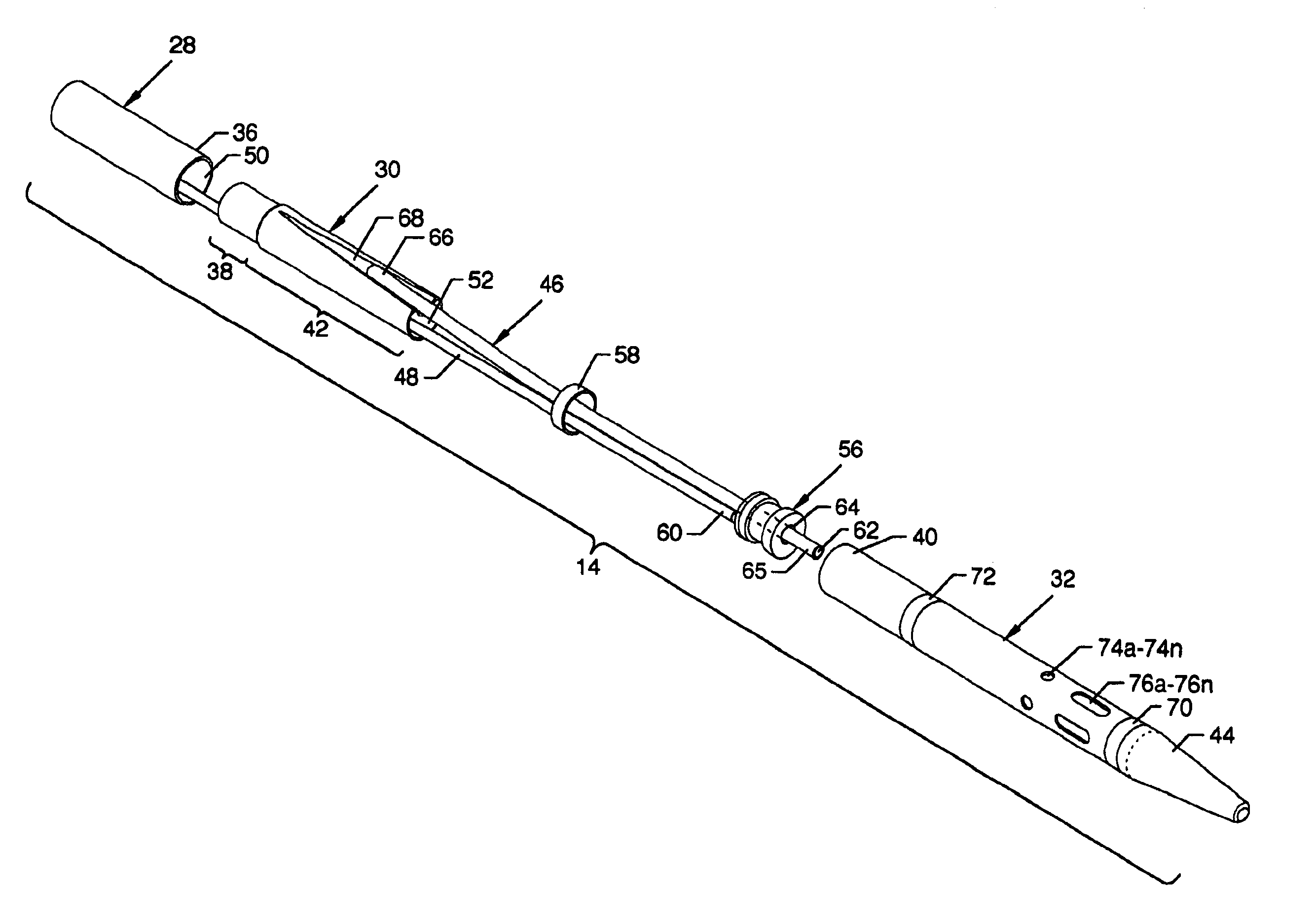
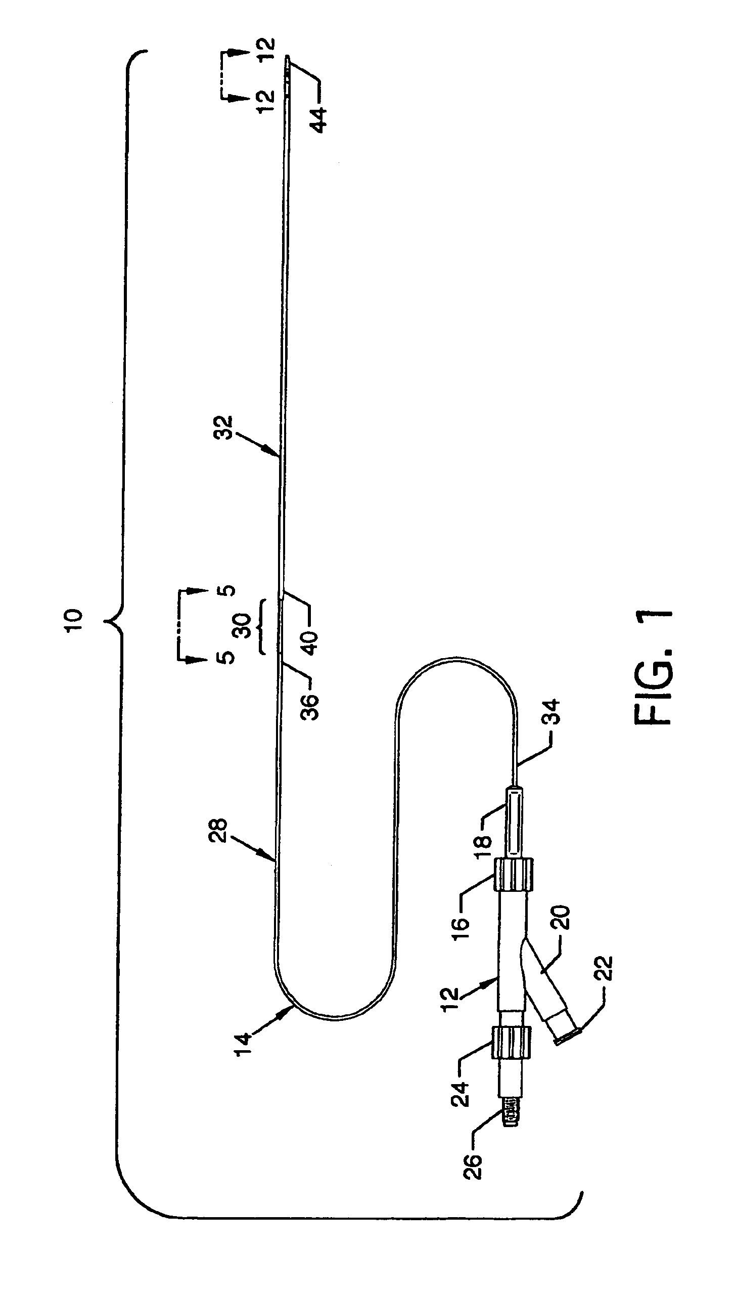
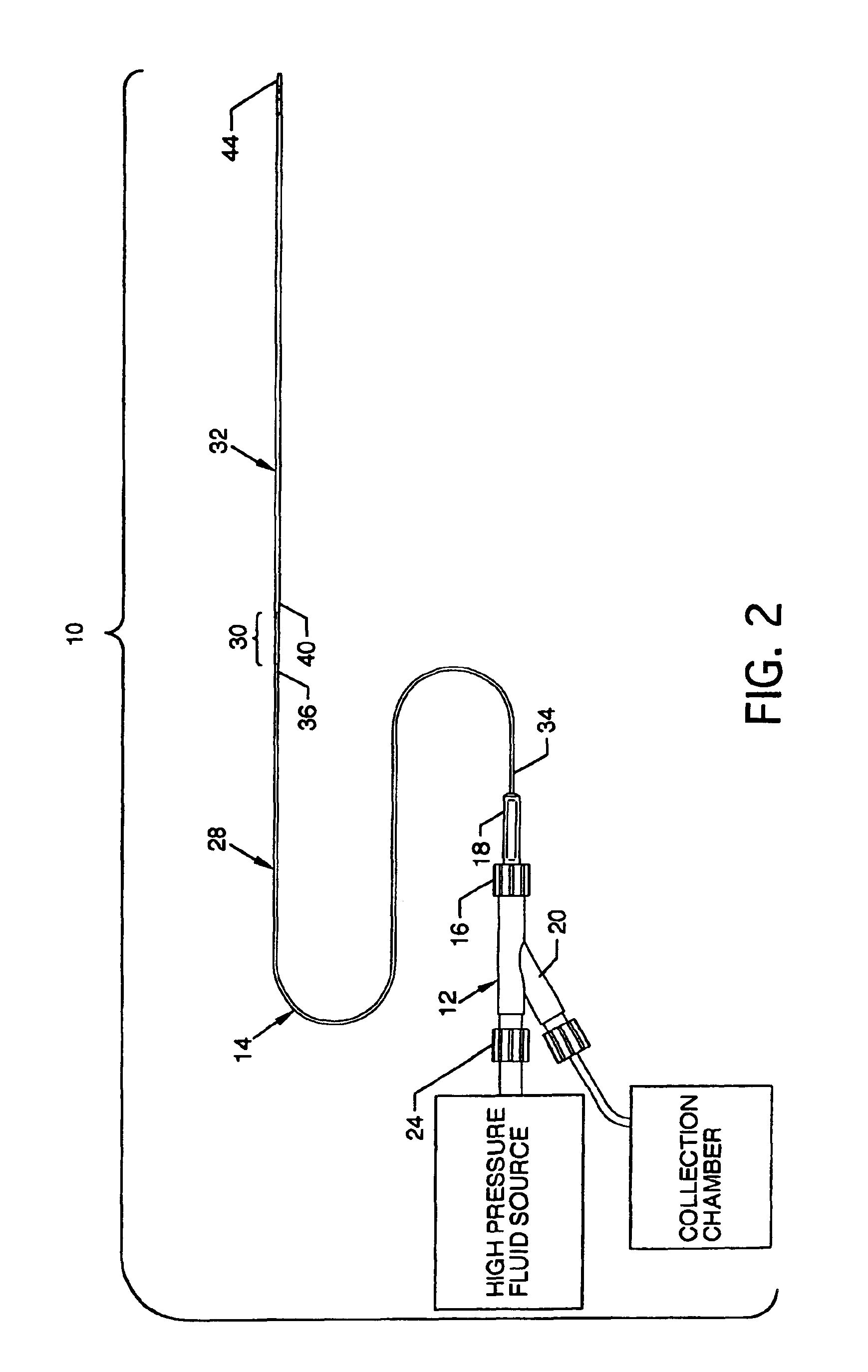
FIG. 1 illustrates a plan view of the visible components of a rapid exchange fluid jet thrombectomy device 10, the present invention, including a manifold 12 and a catheter 14. The manifold 12 includes a distally located Luer fitting 16 and strain relief 18, an exhaust branch 20 and threaded branch end 22, a proximally located Luer fitting 24, and threaded high pressure connection port 26. The catheter 14, a unitary elongated structure, extends distally from the strain relief 18 and includes multiple components comprising, but not limited to, a one-piece proximal exhaust tube 28, a one-piece semi-rigid intermediate tube 30, and a one-piece distal exhaust tube 32 connected in series fashion, a guidewire tube 46 (FIG. 3), and other features and components as described herein. The proximal exhaust tube 28 and the distal exhaust tube 32 are fashioned of braided polyimide to provide for minimal wall thickness for improved free exhaust and dye flow characteristics, while still maintaining...


PUM


Abstract

A rapid exchange fluid jet thrombectomy device for removal of thrombus or unwanted tissue debris from a vein, artery or the like. The device includes a semi-rigid intermediate tube between a proximal and a distal exhaust tube which accommodates a guidewire tube exit located along the catheter at less than one-half the length of the catheter measured from the catheter most distal point. Such a location of the guidewire is convenient for maneuvering and longitudinal advancement of the guidewire, as well as maneuvering and longitudinal advancement of the catheter by one practitioner.

Description

BACKGROUND OF THE INVENTION1. Field of the InventionThe present invention relates to a rapid exchange catheter, such as a fluid jet material removal catheter and system, to a method of constructing same, and to a method of using same in diagnosis or treatment of a body vessel or other body cavity or tissue.The present invention relates to apparatus for use in treatment of the human body. More particularly, the present invention relates to an elongated device which may be a single catheter assembly or a multiple component catheter assembly and which is suitable for use through percutaneous or other access, for endoscopic procedures, or for intraoperative use in either open or limited access surgical procedures. Still more particularly, the present invention relates to an elongated device in the form of a fluid jet thrombectomy catheter, being adapted for fragmentation and removal of thrombus or other unwanted material from blood vessels or body cavities by using high velocity saline ...

Claims


Application Information

Patent Timeline
IPC IPC(8): A61B17/22A61B19/00A61B17/00A61M25/00
CPCA61B17/22A61B17/3203A61B17/32037A61B2019/304A61B2017/00778A61B2017/22041A61B2017/00292A61B2090/034
Inventor BONNETTE, MICHAEL JOHNTHOR, ERIC JOELWEISEL, STEPHEN EARLWONG, AMANDA J.
Owner BOSTON SCI LTD
Why Eureka
Try Eureka