
High shear rotating disc filter

a technology of rotating discs and filters, applied in the field of filters, can solve the problems of higher filtering capacity of filters, and achieve the effects of high shear, increased surface area of filtering media, and higher filtering capacity

Inactive Publication Date: 2005-03-29
SCHEPIS ANTHONY
View PDF17 Cites 17 Cited by
  • Summary
  • Abstract
  • Description
  • Claims
  • Application Information

AI Technical Summary

Benefits of technology

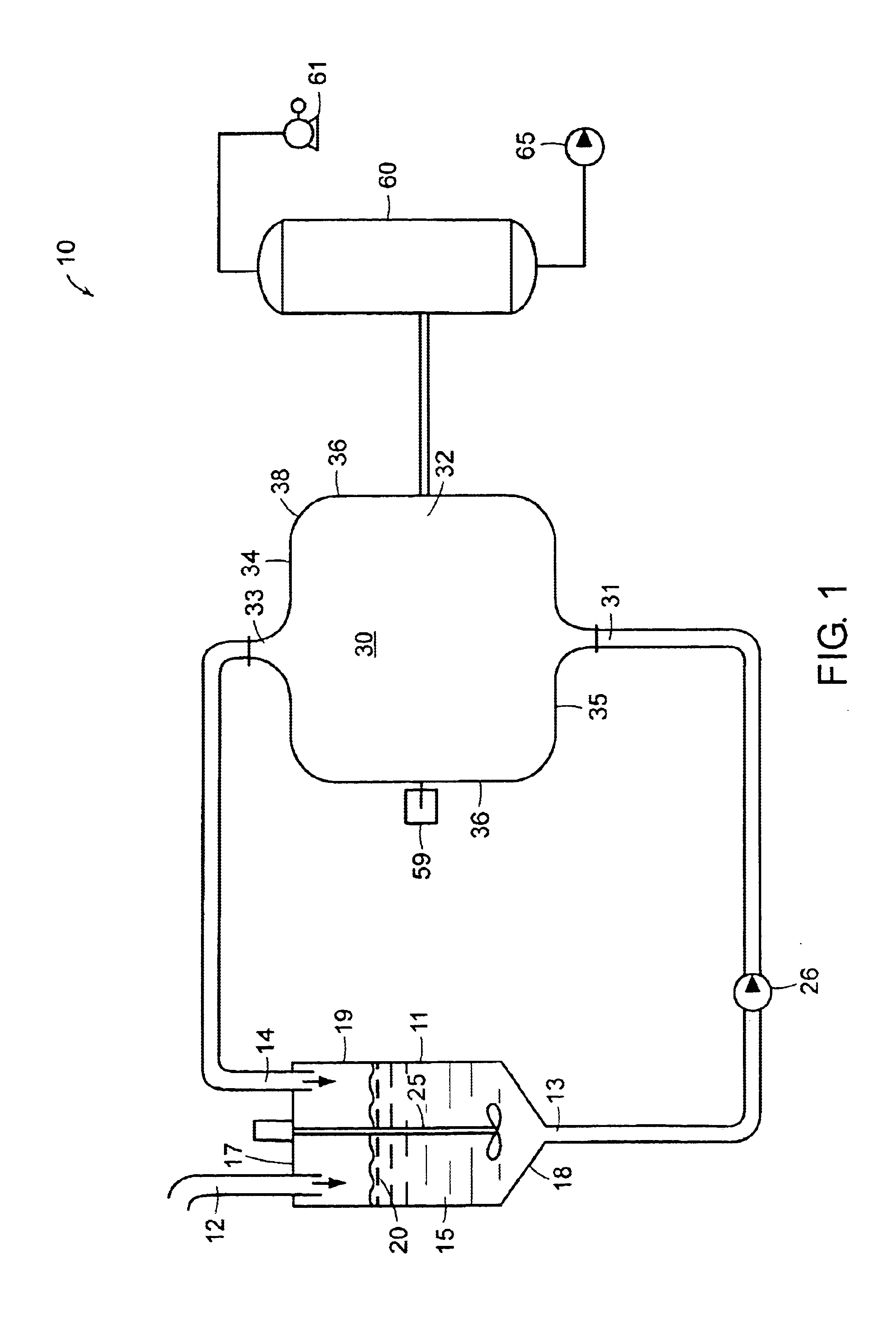
[0017]By concentrating the solids content of a given slurry on a continuous basis, the present invention is able to greatly reduce the liquid loading that needs to be processed. This reduces the handling cost of the slurry and improves separation efficiency. Due to the present invention's shearing effect, the concentration is done without the assistance of a filter-aid thereby eliminating that part of the cost burden as well as the handling and disposal of the contaminated solids.
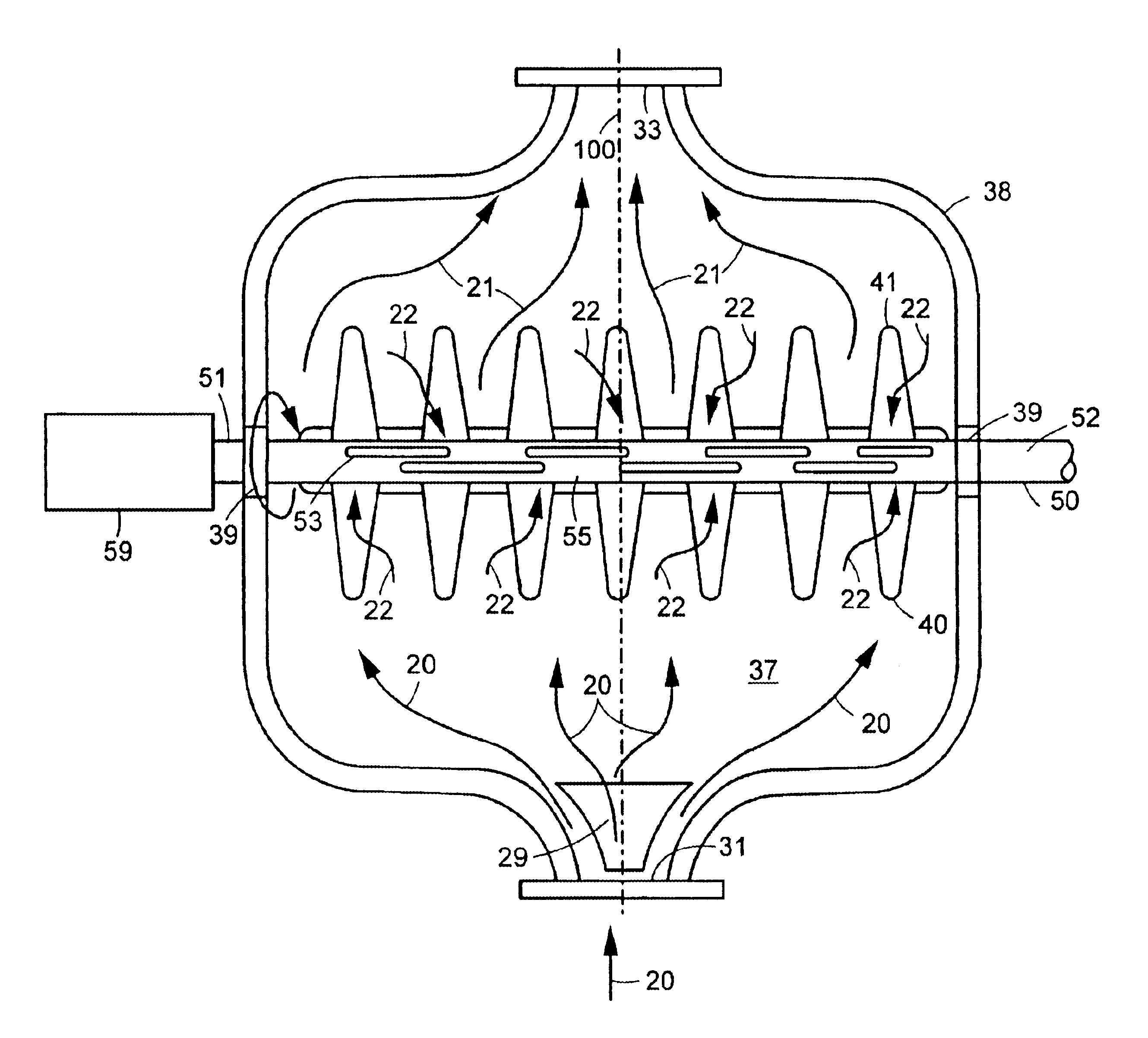
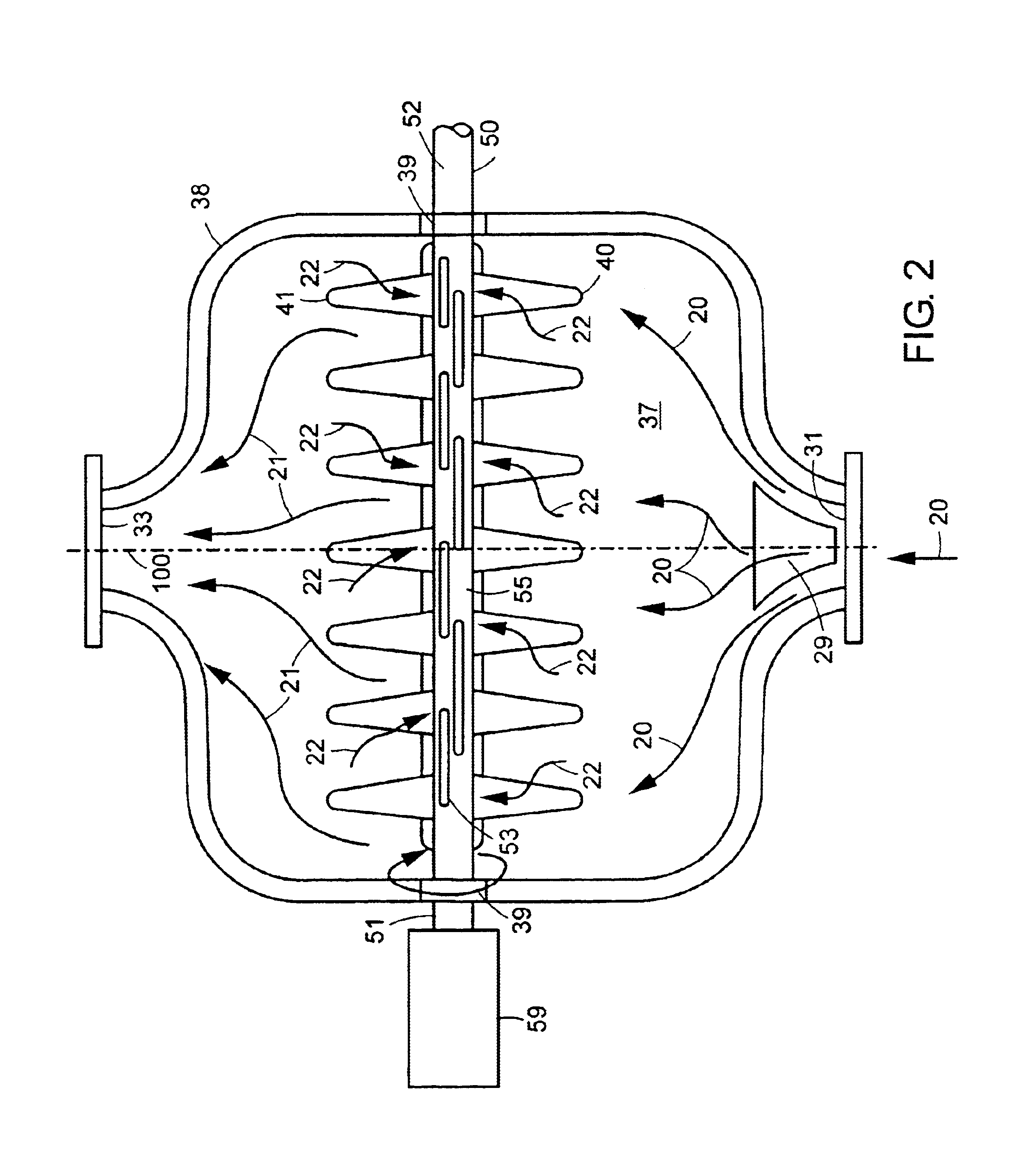
[0019]The high shear can also be achieved even if it were a cylindrical tube. However, using a disc increases the surface area of the filtering medium, thereby resulting in the filter's higher filtrate capacity.

Problems solved by technology

However, using a disc increases the surface area of the filtering medium, thereby resulting in the filter's higher filtrate capacity.

Method used


Image

  • High shear rotating disc filter
  • High shear rotating disc filter
  • High shear rotating disc filter

Examples


Embodiment Construction

[0026]Referring to the drawings in detail wherein like elements are indicated by like numerals, there is shown in FIG. 1 a basic filtering system 10 using a high shear rotating disc filter assembly 30. The system 10 has a feed tank 11 with a top 17 (either open or closed), bottom 18 and side wall 19 extending upward from the bottom 18 and terminating at the top 17, said top 17, bottom 18 and side wall 19 defining a feed tank interior 15. The feed tank 11 has an input means 12 at the tank top 17, an output means 13 at the tank bottom 18, and recycle input means 14 at the tank top 17. The feed tank 11 also has a mixing means 25 extending into the tank interior 15. The feed tank 11 acts as a holding tank for the “slurry to be filtered”20. The slurry 20 contains liquid and very small particles 23. The mixer 25 provides homogeneity to the feed slurry 20. The slurry 20 to be filtered is drawn out of the feed tank 11 through the tank output means 13 at the tank bottom 18 by a feed pump 26....


PUM

PropertyMeasurementUnit
particle sizeaaaaaaaaaa
perimeteraaaaaaaaaa
particle size distributionaaaaaaaaaa

Abstract

A high shear rotating disc filter having a hollow interior and constructed of a porous material such as sintered metal or ceramic with finely structured openings. The disc is mounted and secured onto a hollow shaft. The hollow shaft is connected to a vacuum source, external to the filter, that allows for the passage of the filtrate to a receiver. There are elongated slots in the wall of the shaft which provide the passage of filtrate from the disc. The shaft provides rotational force for the discs.

Description

BACKGROUND OF THE INVENTION[0002]This invention relates to filters, and in particular to a high shear rotating disc filter.[0003]Current filtering technologies cover a wide gamut of designs for a wide variety of liquid / solid separating applications. Solids refer to small particles as in powders. These technologies are necessitated by the many filtering characteristics of the liquid / solid mixtures or slurries which are being separated. a slurry being defined as a liquid solid mixture. Such characteristics will include particle size distribution, particle shapes, particle hardness / softness, solids concentration, liquid viscosity, flow rate slurry temperature, degree of separation required, etc. However, each filtering technology has its operation and economic limitations. Commonly used filters include: filter press with and without membrane bladders, candle filters, leaf filters (vertical and horizontal), nutsche type filters, rotary vacuum filters, vacuum disc filters, etc.[0004]With...

Claims


Application Information

Patent Timeline
Patent Type & Authority Patents(United States)
IPC IPC(8): B01D33/21B01D35/30B01D37/00
CPCB01D33/21B01D35/30B01D37/00B01D33/48B01D33/56
Inventor SCHEPIS, ANTHONY
Owner SCHEPIS ANTHONY
Learn More