
Electronic sphygmomanometer

a sphygmomanometer and electronic technology, applied in the field of sphygmomanometers, can solve the problems of affecting the accuracy of blood pressure measurement, and becoming impossible to precisely measure blood pressur

Inactive Publication Date: 2005-03-29
OMRON HEALTHCARE CO LTD
View PDF13 Cites 31 Cited by
  • Summary
  • Abstract
  • Description
  • Claims
  • Application Information

AI Technical Summary

Benefits of technology

With this electronic sphygmomanometer, the posture of the subject person is detected using the altitude of the measurement region and the inputted living body information of the subject person. As a result, it becomes possible to determine whether measurement is proper or not without being affected by physical variations among subject persons.
With this electronic sphygmomanometer, the posture of the subject person is detected using an angle of the measurement region and the inputted living body information of the subject person, and the measured blood pressure value is corrected using this detected posture. As a result, it becomes possible to precisely measure a blood pressure without being affected by physical variations among subject persons.
With this electronic sphygmomanometer, the upper arm angle measuring means that is separated from the main body detects the angle of the upper arm. Therefore, the angle of an arm as well as the angle of a forearm are reflected in the calculation of the positional relation between a cuff and a heart with regard to the altitudes thereof. As a result, it becomes possible to determine whether measurement is proper or not without being affected by the inclination of the upper arm.
With this electronic sphygmomanometer, the upper arm angle detecting means that is separated from the main body detects the angle of the upper arm and the angle of the upper arm as well as the angle of a forearm are reflected in the calculation of the positional relation between a cuff and a heart with regard to the altitudes thereof. Then, a blood pressure value is precisely corrected. As a result, it becomes possible to precisely measure a blood pressure without being affected by inclination of the upper arm.
Another electronic sphygmomanometer of the present invention comprises: measuring means that is placed on a predetermined region and measures one of a blood pressure and hemodynamics; biaxial angle detecting means for detecting angles of two axes; measurement posture altitude difference calculating means for calculating an altitude difference in a vertical direction between a heart of a subject person and a predetermined reference position of the sphygmomanometer using the angle detected by the biaxial angle detecting means; measurement posture propriety determining means for determining whether the calculated altitude difference exists within a predetermined altitude difference range using a result of the calculation by the measurement posture altitude difference calculating means; and notifying means for notifying the subject person of a result of the determination by the measurement posture propriety determining means. By detecting the angles of two axes in this manner, it becomes possible to more precisely calculate the altitude difference in the vertical direction between the heart of the subject person and the predetermined reference position of the sphygmomanometer. As a result, it becomes possible to more exactly determine a measurement posture.
Also, another electronic sphygmomanometer of the present invention comprises: measuring means that is placed on a predetermined region and measures one of a blood pressure and hemodynamics; biaxial angle detecting means for detecting angles of two axes; measurement posture altitude difference calculating means for calculating an altitude difference in a vertical direction between a heart of a subject person and a predetermined reference position of the sphygmomanometer using the angle detected by the biaxial angle detecting means; correction pressure calculating means for calculating a correction value for a blood pressure using a result of the calculation by the measurement posture altitude difference calculating means; post-correction blood pressure calculating means for calculating a post-correction blood pressure value using the correction value calculated by the correction pressure calculating means and a blood pressure value measured by the measuring means; and measurement result notifying means for notifying the subject person of a result of the calculation by the post-correction blood pressure calculating means. By detecting the angles of two axes in this manner, it becomes possible to precisely calculate the altitude difference in the vertical direction between the heart of the subject person and the predetermined reference position of the sphygmomanometer. A blood pressure value is corrected on the basis of a value obtained as a result of this calculation, so that it becomes possible to more precisely measure a blood pressure.

Problems solved by technology

Therefore, there may be cases where it becomes impossible to precisely measure blood pressures.
However, if the positional relation between the heart and the cuff is determined only from uniaxial angle information like in the case of the conventional technique described above, various error causing factors affect the accuracy of the blood pressure measurement.
Accordingly, if it is determined that this detected inclination angle is correct, there may be a case where it becomes impossible to precisely measure a blood pressure due to the variation in forearm length.
Accordingly, if it is determined that this inclination angle is correct, there may be a case where it becomes impossible to precisely measure a blood pressure due to the variation in upper arm length.
Accordingly, if it is determined that the altitude of the cuff is the same as the altitude of the heart in the cases shown in FIGS. 34B and 35 because the inclination angle of the forearm L1 is the same as that shown in FIG. 34A, there occurs a problem in that erroneous results are obtained.
There may be the cases where this causes an error.

Method used


Image

  • Electronic sphygmomanometer
  • Electronic sphygmomanometer
  • Electronic sphygmomanometer

Examples


first embodiment

(First Embodiment)

The present invention will be described in more detail below by means of embodiments.

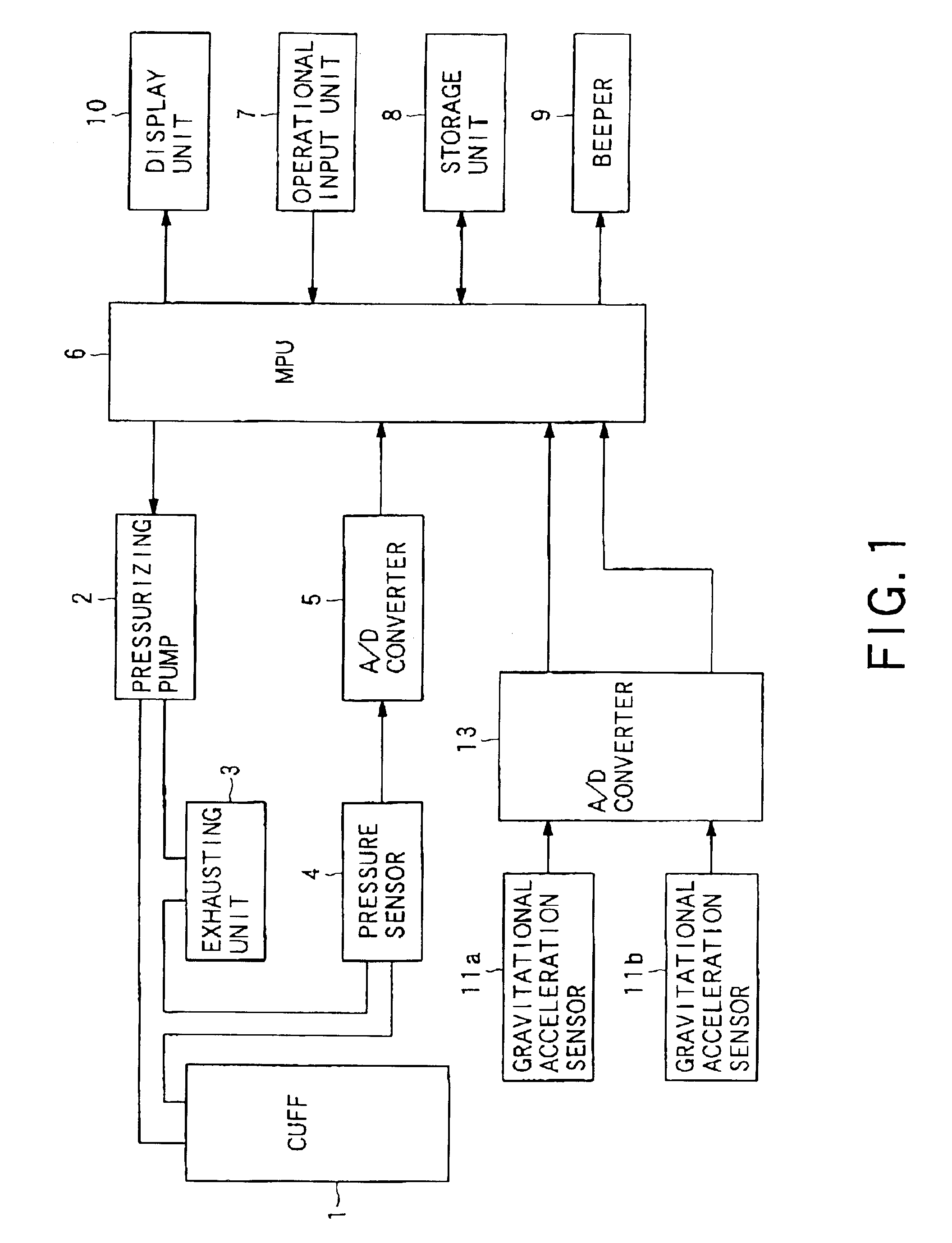
FIG. 1 is a block diagram showing the hardware construction of an electronic sphygmomanometer according to the first embodiment of the present invention. This electronic sphygmomanometer includes: a cuff 1; a pressurizing pump 2 for pressurizing this cuff 1; and exhausting unit 3 for exhausting air from the cuff1; a pressure sensor 4 for detecting an air pressure in the cuff 1; an A / D converter 5; an MPU 6 that performs processing for measuring a blood pressure by executing an installed program; an operational input unit 7 including a pressurizing key, keys for inputting a forearm length and an upper arm length, and other keys; a storage unit if the body is inclined while maintaining the same angle of a forearm in the pitch direction, the positional relation between the heart and the main body changes in the vertical direction. It is possible to reduce an altitude dejection error d...

second embodiment

(Second Embodiment)

FIG. 7 is a block diagram showing the functional construction of an electronic sphygmomanometer according to the second embodiment of the present invention. The electronic sphygmomanometer according to this embodiment includes; a pressure detecting unit 20 including a pressure sensor 4; a pressure pulse wave detecting unit 31; a blood pressure calculating unit 30 including a blood pressure value calculating unit 32; an upper arm and forearm length inputting means 8a; an angle sensor 11; a forearm angle detecting unit 41; a posture detecting unit 40 including a cuff altitude detecting unit 42; a correction value calculating unit 51; a blood pressure correcting unit 50 including a blood pressure value correcting unit 52; and a display unit 10. The hardware construction of the electronic sphygmomanometer according to this embodiment is the same as that shown in FIG. 1. The function of each of the pressure pulse wave detecting unit 31, the blood pressure value calcula...

third embodiment

(Third Embodiment)

FIG. 15 shows a state where an electronic sphygmomanometer of the third embodiment of the present invention is placed. The electronic sphygmomanometer according to this embodiment includes a sphygmomanometer main body 21 and an upper arm angle measuring unit 22. The sphygmomanometer main body 21 and the upper arm angle measuring unit 22 include infrared transmission and reception devices 23 and 24, respectively, and perform data exchange by performing wireless communications using infrared rays 25.

FIG. 16 is a block diagram showing the hardware construction of the electronic sphygmomanometer according to this embodiment. This electronic sphygmomanometer includes: a cuff1; a pressurizing pump2 for pressurizing this cuff 1; an exhausting unit 3 for exhausting air from the cuff 1; a pressure sensor 4 for detecting an air pressure in the cuff 1; an A / D converter 5; an MPU 6 that performs processing for measuring a blood pressure by executing an installed program; an op...


PUM


Abstract

Blood pressure measurement is precisely performed by more correctly determining positions of a cuff and a heart without being affected by variations in physical features among subject persons and their postures during the measurement. With the technique of the present invention, there are calculated the altitudes of the cuff and the heart on the basis of an inputted upper arm length and forearm length of a subject person and forearm angles detected in the pitch direction and roll direction. Also, in addition to a forearm angle detecting means, an upper arm angle detecting means is provided and the altitudes of the cuff and the heart are calculated on the basis of detected angles of a forearm and an upper arm. Also, a biaxial angle detecting means detects angles of the forearm in the pitch direction and the roll direction and calculates the altitudes of the cuff and the heart on the basis of these detected values.

Description

TECHNICAL FIELDThe present invention relates to an electronic sphygmomanometer having a function of detecting the posture of a subject person.BACKGROUND ARTIt is possible for a general sphygmomanometer to obtain a precise blood pressure value when blood pressure measurement is performed under a condition where a cuff is raised and the altitude thereof becomes the same as the altitude of a heart. However, in the case of an electronic sphygmomanometer applied to a wrist, an electronic sphygmomanometer applied to a finger, or the like, the sphygmomanometer is used under a condition where a cuff (integrated with a main body in many cases) is placed on the wrist, finger, or another predetermined region. The wrist and finger are regions that are capable of freely moving, so that it is impossible to set these parts so that the altitudes thereof become the same as the altitude of a heart. Therefore, there may be cases where it becomes impossible to precisely measure blood pressures.To avoid...

Claims


Application Information

Patent Timeline
Patent Type & Authority Patents(United States)
IPC IPC(8): A61B5/022A61B5/103A61B5/021
CPCA61B5/021A61B5/02116A61B5/1071A61B5/1116A61B5/681A61B5/1072A61B5/103A61B5/6824A61B2560/0261A61B5/022
Inventor KATO, HIROYUKITANAKA, TAKAHIDESANO, YOSHIHIKOOKU, SHOJIRO
Owner OMRON HEALTHCARE CO LTD
Learn More