
Divider assembly for a drawer

a technology for dividers and drawers, applied in the field of dividers, can solve the problems of not fully utilizing drawer space nor being readily changeable, known dividers do not always provide components, and are impractical, so as to prevent undesired shifting or separation of joined components, the effect of facilitating sizing

Inactive Publication Date: 2005-03-29
ERNST GREGORY R
View PDF8 Cites 70 Cited by
  • Summary
  • Abstract
  • Description
  • Claims
  • Application Information

AI Technical Summary

Benefits of technology

The present divider assembly utilizes components that permit selective positioning of divider rails and rails forming the perimeter of the assembly in a rapid but secure manner to prevent undesired shifting or separation of joined components. Projections and recesses on the components permit snapped engagement of same by manual effort and taking advantage of the somewhat yieldable nature of the molded components. Rails of the assembly permit sizing of same to adapt the assembly to a wide range of drawer sizes. Provision is made in the divider rails and divider clips to accept rails cut by the installer to less than exact dimensions to facilitate sizing and assembly of the present divider assembly to suit specific drawer sizes. Clips attaching a divider rail to a perimeter rail are snapped into place without the aid of tools.

Problems solved by technology

A problem exists in the provision of storage areas within tool box or tool cabinet drawers wherein it is frequently desirable that each drawer has several storage areas of different sizes for the size and number of components to be stored.
Known dividers are impractical in that they often do not fully utilize drawer space nor are they readily changeable to accommodate a wide range of different sized articles.
Further, known dividers do not always provide components that resist shifting within the tool box or tool chest drawer and do not lend themselves to rapid removal, reconfiguration and reinstallation in a drawer.

Method used


Image

  • Divider assembly for a drawer
  • Divider assembly for a drawer
  • Divider assembly for a drawer

Examples


Embodiment Construction

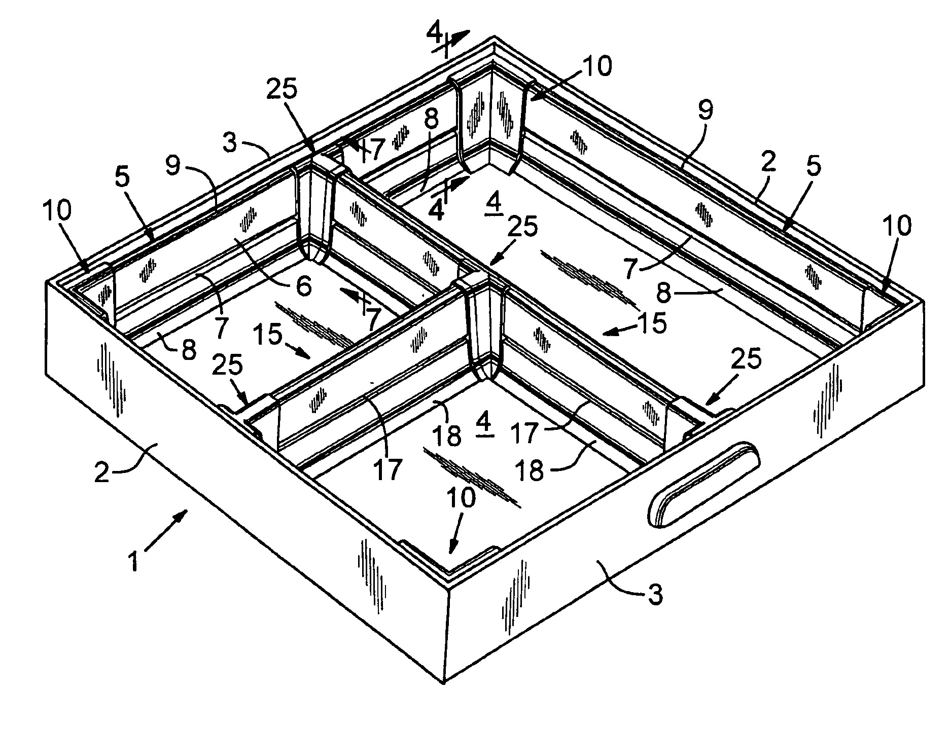
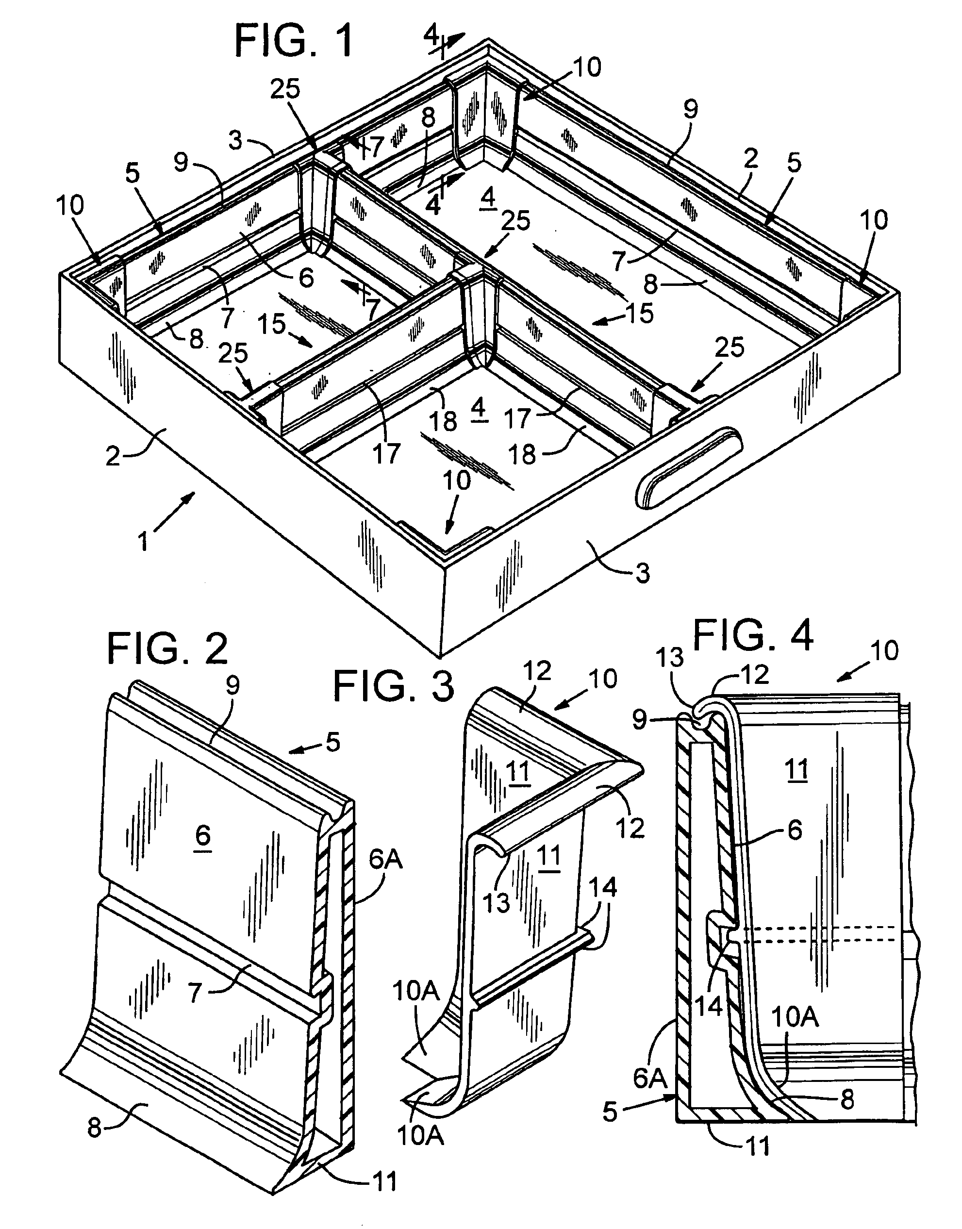
With continuing attention to the drawings wherein applied reference numerals indicate parts similarly hereinafter identified, the reference numeral 1 indicates generally a drawer having sides 2, and front and rear components 3, and a bottom wall 4. Drawer 1 is typical of drawers found in various types of cabinets including tool cabinets and tool boxes. Appendages for slidably mounting such a drawer are not shown.

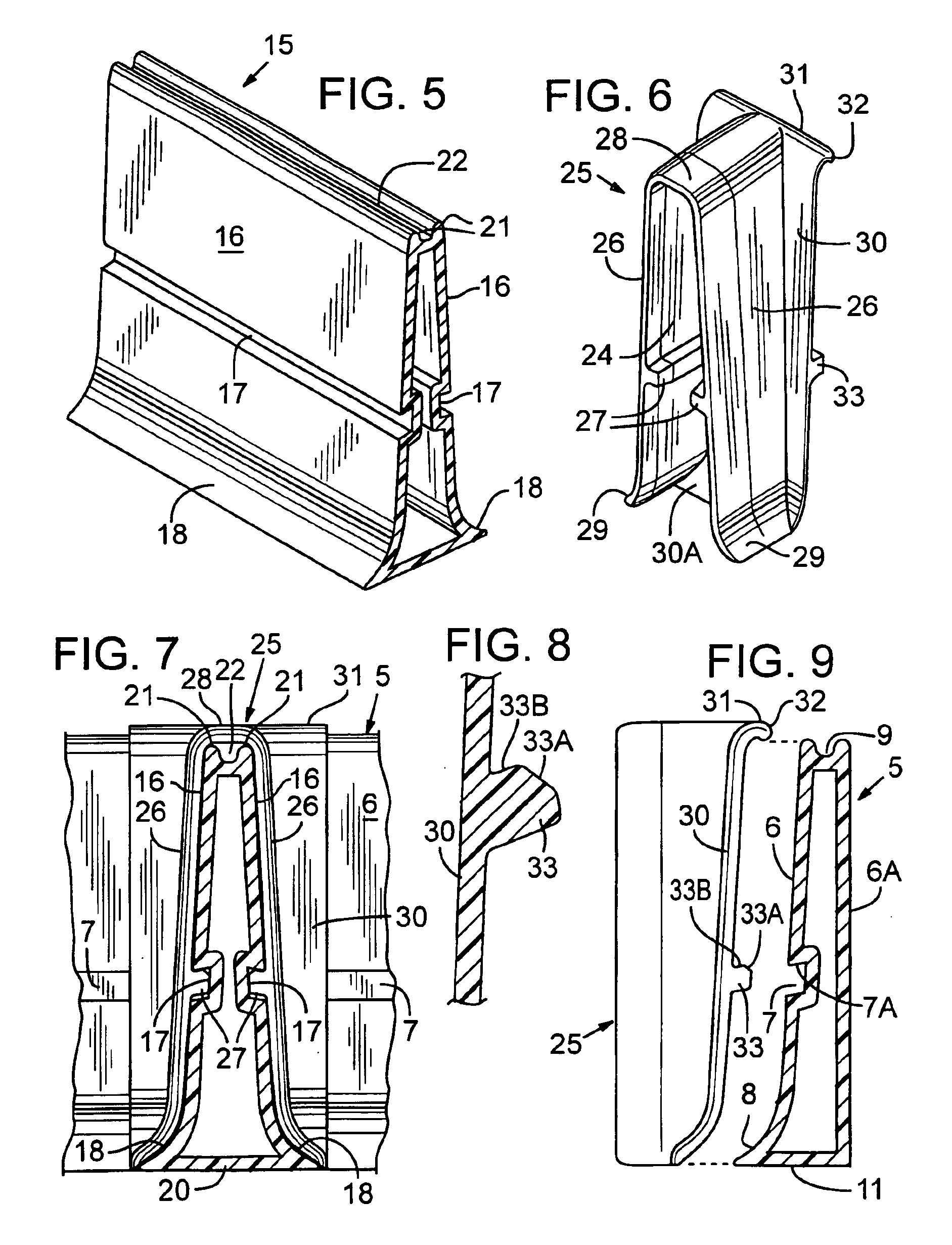
With attention now to the present divider assembly, the reference numeral 5 indicates a perimeter rail in place on a drawer bottom wall 4. With attention additionally to FIG. 2, it will be seen that a perimeter rail has an upright wall 6 while a channel or recess 7 extends lengthwise of the wall. A bottom portion of wall 6 preferably includes an inwardly sloped segment 8 to facilitate grasping of loose articles stored in an area partially defined by perimeter wall 5. The wall terminates upwardly in a lengthwise top groove at 9. When in place on a drawer bottom, a back wall 6...


PUM


Abstract

A divider assembly for installation in a tool box or chest drawer to provide separate drawer areas for the storage of various grouped articles. Perimeter rails are joined by corner clips to maintain a rectangular shape of the divider assembly. Divider rails extend intermediate perimeter rails to form storage areas of various shapes and sizes. Divider clips receive the divider rail ends. Projections and recesses on the divider clips and the perimeter rail members confine the divider rails against displacement. Flexure of the divider clips permit snapped engagement of the clips with the perimeter rail member.

Description

BACKGROUND OF THE INVENTIONThe present invention concerns generally a divider permitting the forming of multiple storage areas within a drawer.A problem exists in the provision of storage areas within tool box or tool cabinet drawers wherein it is frequently desirable that each drawer has several storage areas of different sizes for the size and number of components to be stored. Known dividers are impractical in that they often do not fully utilize drawer space nor are they readily changeable to accommodate a wide range of different sized articles. Further, known dividers do not always provide components that resist shifting within the tool box or tool chest drawer and do not lend themselves to rapid removal, reconfiguration and reinstallation in a drawer. A still further shortcoming of known dividers is that they result in a right angular intersection of a divider vertical surface and the drawer bottom hindering the removal of a specific small article from the drawer.SUMMARY OF TH...

Claims


Application Information

Patent Timeline
Patent Type & Authority Patents(United States)
IPC IPC(8): A47B88/20A47B88/00
CPCA47B88/20A47B88/975A47B88/994A47B88/90
Inventor ERNST, GREGORY R.
Owner ERNST GREGORY R
Learn More