
Modular building connector

a technology of building connection and module, applied in the direction of special buildings, human health protection, foundation engineering, etc., can solve the problems of unbalanced building deformation, connectors located in certain areas of buildings are likely to be subject to much greater forces than other connectors, and the connection may move more than other connectors, so as to achieve the effect of “tune” the building structure and better resist destructive forces

Inactive Publication Date: 2005-03-29
LOCKE REGINALD A J
View PDF44 Cites 28 Cited by
  • Summary
  • Abstract
  • Description
  • Claims
  • Application Information

AI Technical Summary

Benefits of technology

An improved modular building connection system is disclosed, including a plurality of connectors having bearing surfaces of different slopes. The different slopes of the bearing surfaces help to compensate for the different forces encountered by the connectors at various locations of the building.
In accordance with yet another aspect of the present invention, a method of constructing a building is provided. The method includes positioning a plurality of connectors between a plurality of structural members of the building. Each of the connectors has an upper portion, a lower portion, a flange extending outwardly between the upper portion and the lower portion, and an axial bore. Each of the upper and lower portions defines a sloped bearing surface. The bearing surfaces of some of the connectors have different slopes than the bearing surfaces of other connectors. Tensioners are then provided through the bores of the connectors to connect the structural members. These tensioners can be adjusted according to computerized design analysis to effectively “tune” the building structure to better resist destructive forces including harmonic vibrations.

Problems solved by technology

One problem with the connection system disclosed in Locke is that connectors located in certain areas of the building are likely to be subjected to much greater forces than connectors located in other areas of the building.
As a result, when external forces are applied to the building, some connectors may move more than other connectors.
Building deformation is thus unbalanced and more difficult to predict, making reasonably accurate computer modeling of the building more difficult.

Method used


Image

  • Modular building connector
  • Modular building connector
  • Modular building connector

Examples


Embodiment Construction

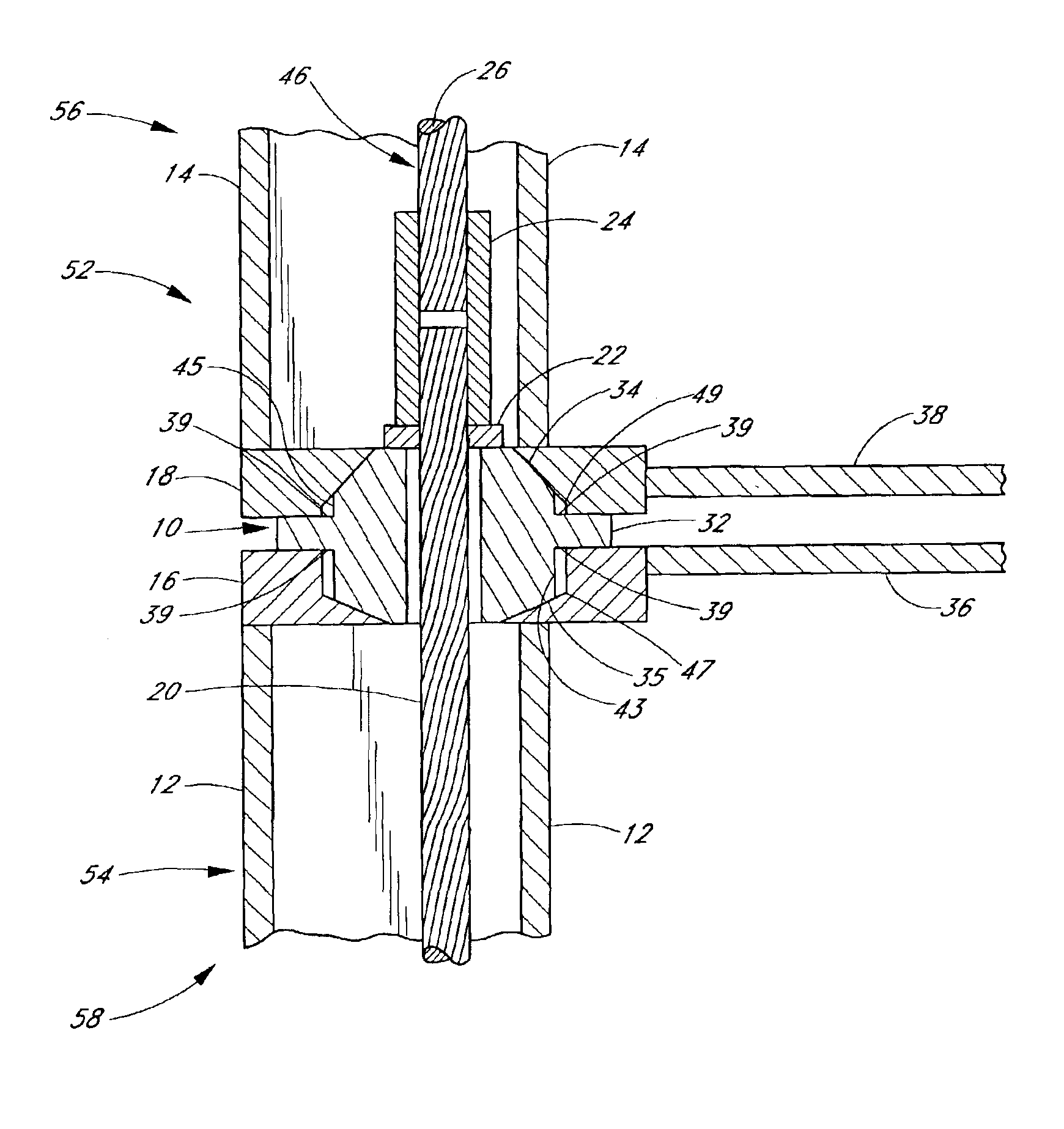
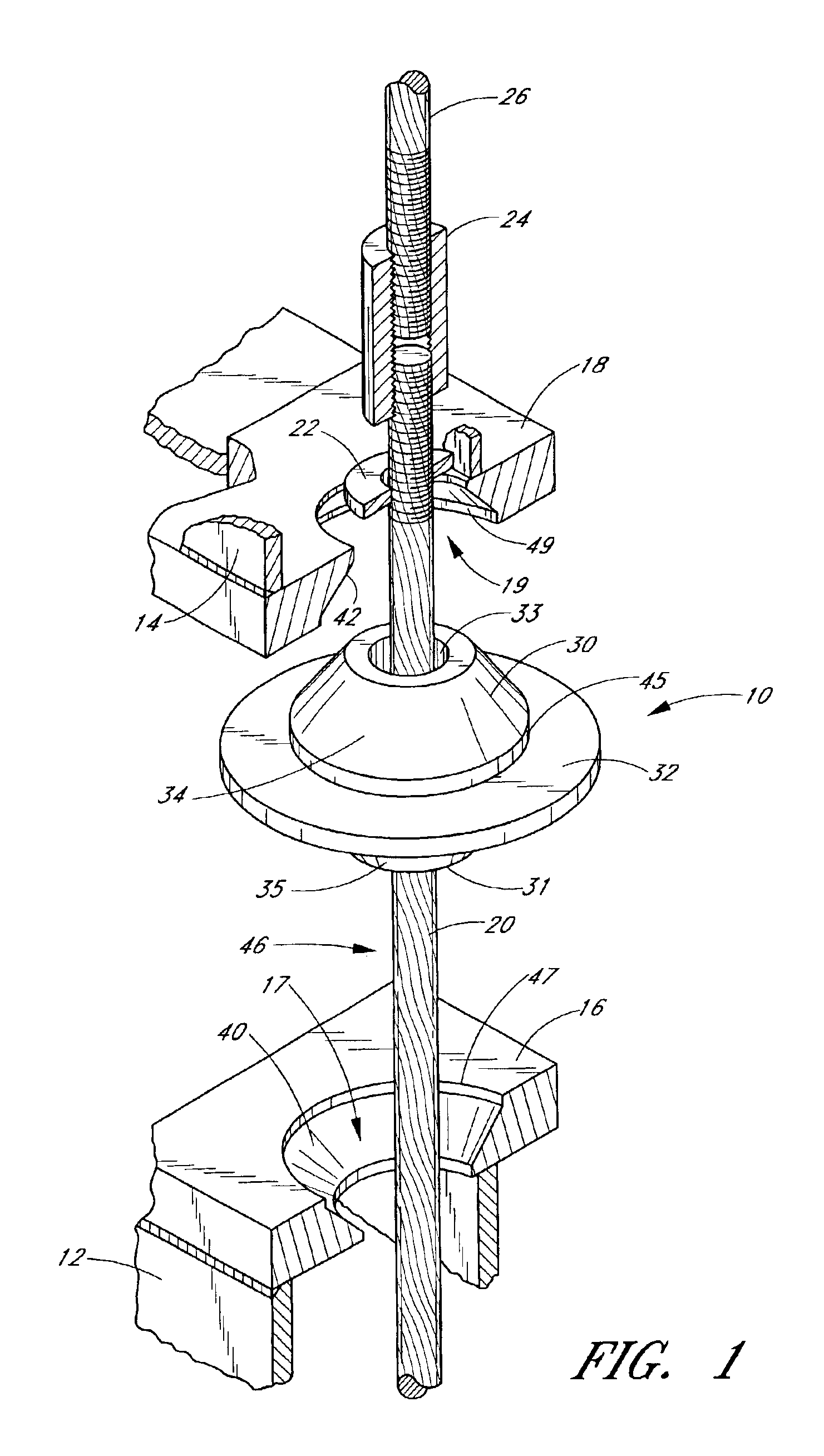
With reference to FIG. 1, a connector 10 is illustrated having an upper portion 30, a lower portion 31, and a flange 32 extending outwardly between the upper portion 30 and the lower portion 31. A bore 33 extends axially through the connector 10 from the upper portion 30 to the lower portion 31.

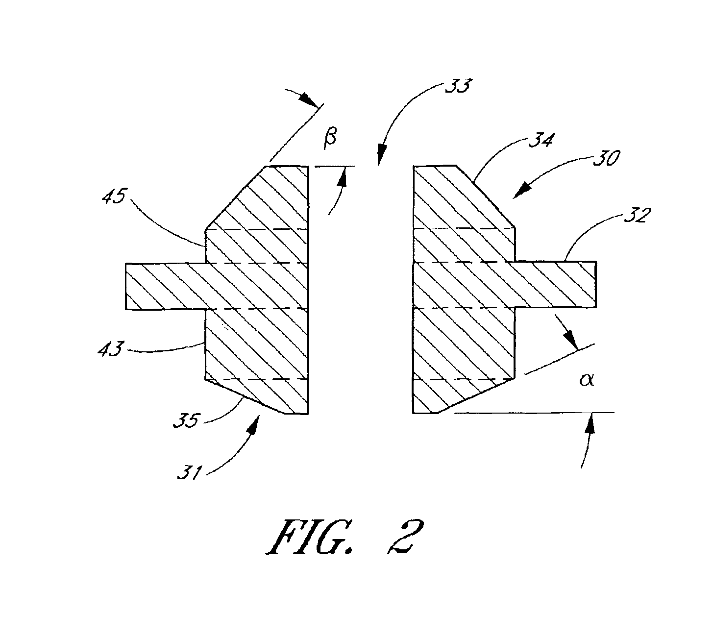
As best illustrated in FIG. 2, in the embodiment shown, the upper and lower portions 30, 31 are generally conical. The upper portion 30 defines an upper bearing surface 34 and upper vertical portion 45, and the lower portion defines a lower bearing surface 35 and lower vertical portion 43. The upper and lower bearing surfaces 34, 35 are sloped relative to the flange 32. In the connector of FIG. 2, the upper bearing surface 34 has a slope β relative to the flange 32, and the lower bearing surface 35 has a slope α relative to the flange 32. The connector 10 is preferably molded with a conventional sintered powder metal process to reduce production costs in comparison with machining. The powdere...


PUM


Abstract

A building construction is provided, including a plurality of connectors. Each of the connectors has an upper portion, a lower portion, a flange extending outwardly between the upper portion and the lower portion, and an axial bore extending through the connector from the upper portion to the lower portion. The upper portion and the lower portion define sloped bearing surfaces. The connectors are positioned between a plurality of building structural members. The upper and lower portions of the connectors extend into recesses in the structural members having sloped walls corresponding to the sloped bearing surfaces of the connectors. A tensioner extends through the bores of the connectors to connect the structural members. The bearing surfaces of at least two of the connectors have different slopes.

Description

FIELD OF THE INVENTIONThe invention relates to modular building connection systems for reinforcing buildings.BACKGROUND OF THE INVENTIONModular building connection systems are used to reinforce buildings against external forces, such as those experienced during earthquakes or severe weather. One example of a modular building connection system is disclosed in U.S. Pat. No. 4,694,621 issued to Locke, which is incorporated by reference herein. The system includes a number of connectors, each having a conical upper portion, a conical lower portion, a central flange, and an axial bore. The connectors are positioned between various structural members of the building. Conical recesses are provided in the structural members to engage the upper and lower portions of the connectors. A tensioner is provided through the bores of the connectors to connect the structural members together.As described in the Locke patent, the connection system effectively translates external lateral forces on the ...

Claims


Application Information

Patent Timeline
Patent Type & Authority Patents(United States)
IPC IPC(8): E04B1/20E04B1/348E04B1/22E04H9/14E04B1/35
CPCE04B1/22E04H9/14E04B1/3483E04B2001/3583Y02A50/00E04B1/38E04H1/00
Inventor LOCKE, REGINALD A. J.
Owner LOCKE REGINALD A J
Learn More