
Circuit for transmitting plesiochronous signals in a SDH system

Inactive Publication Date: 2005-03-22
LUCENT TECH INC
View PDF8 Cites 8 Cited by
  • Summary
  • Abstract
  • Description
  • Claims
  • Application Information

AI Technical Summary

Benefits of technology

Thus it is the purpose of the invention to indicate a circuit arrangement for a reception part or for a transmission part of an SDH transmission system, which makes it possible, at a low complexity and at small technical expenditure, to transmit plesiochronous signals in an SDH transmission system.
In an advantageous elaboration, a demultiplexer (reception demultiplexer) follows the reception processing means. Thereby it is possible to connect the circuit arrangement for the reception part without additional technical expenditure to an interface that is connected before the SDH transmission channel. At this interface there is e.g. an SDH multiplexer which receives the synchronized signals from the reception demultiplexer and retransmits them on the SDH transmission channel. It is thereby possible to connect the circuit arrangement for the receiving side without any special technical expenditure to an already provided interface of the SDH transmission channel. This, in turn, raises the universal insertability of the circuit arrangement.
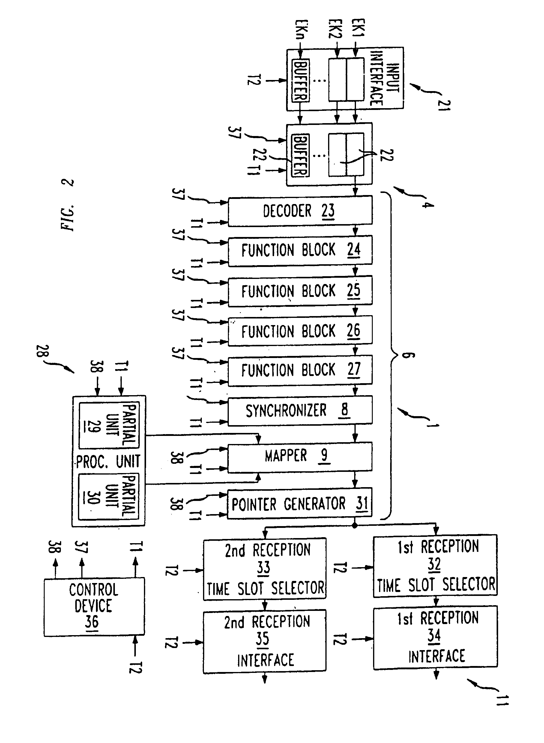
Digital sequential circuits of this kind for the processing of parallel signals thus facilitate the construction of the receiving part and the transmitting part with minor complexity and with minor technical expenditure. At that, compared to previously known sequential circuits, the additional technical expenditure for the state memory is small enough to be negligible in comparison to the savings effect through the multiple use of the same combinatorial logic (combinatorial circuit) in the time multiplex method.
Furthermore, in a preferred form of execution, there is provided for the issuance of the output variables of the combinatorial circuit a first output, which is followed by a first demultiplexer (especially a reception or transmission demultiplexer). By this measure it is possible to read out the states of the combinatorial circuit present in the individual time slices. In an appropriate manner, a second output is provided for the output of the system state, with a second demultiplexer being connected before it. This makes it possible to access the respective present system states in the individual time slices.
So as to be able to carry out a number of processing functions within one component part, to good advantage several combinatorial circuits, each one with an associated state memory, are connected in series. It is thereby possible in a simple way by circuit technology to integrate in the reception processing unit and / or in the transmission processing unit and / or in the desynchronizer several processing functions for processing the signals.

Problems solved by technology

A disadvantage is here the fact that the expenses for the circuit technology increase strongly with the rising number of input channels assigned to the reception part or output channels assigned to the transmission part.

Method used


Image

  • Circuit for transmitting plesiochronous signals in a SDH system
  • Circuit for transmitting plesiochronous signals in a SDH system
  • Circuit for transmitting plesiochronous signals in a SDH system

Examples


Embodiment Construction

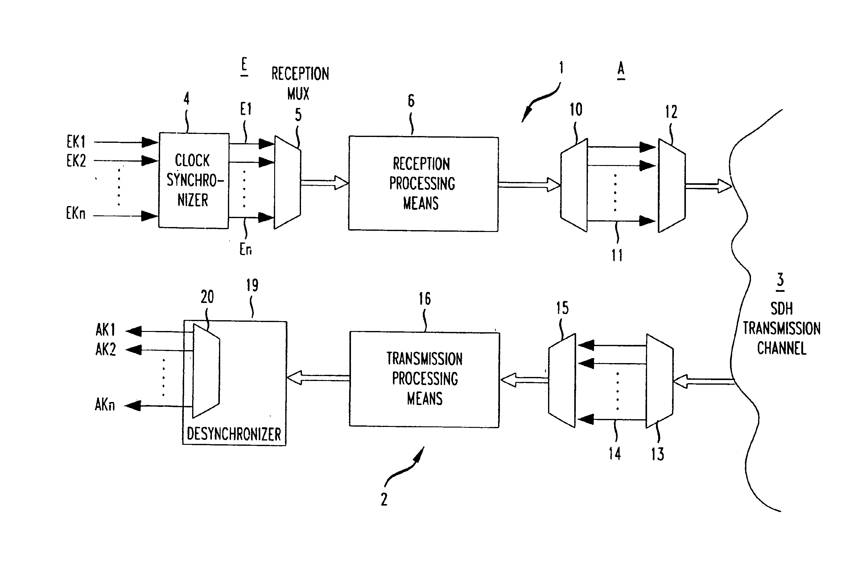
According to FIG. 1, an SDH transmission system contains a circuit arrangement for a receiving part 1 and a circuit arrangement for a transmission part 2. The reception part 1 and the transmission part 2 are connected via suitable interfaces to an SDH transmission channel 3 shown only schematically. By means of the SDH transmission system shown in FIG. 1 parallel plesiochronous signals are received, processed in the reception part 1, and sent out as “synchronized” signals on the SDH transmission channel 3. After the transmission of the “synchronized” signals, the plesiochronous structure of the signals is reconstituted in the transmission part 2 before they are issued by the transmission part 2 to the parallel output channels AK1, AK2. . . .

The reception part 1 receives at its input side several parallel plesiochronous signals. To this end, several mutually parallel input channels EK1, EK2, . . . EKn are arranged. These input channels EK1, EK2, . . . EKn are connected to a clock syn...


PUM


Abstract

A circuit arrangement for a reception part of an SDH transmission system for transmitting plesiochronous signals contains input channels assigned to these signals which are connected to a clock synchronizer for the adaptation of the plesiochronous signals to a common processing clock. The clock synchronizer is followed by a multiplexer, to the output of which a reception processor is connected for the transformation of a plesiochronous signal into a synchronous signal for an SDH transmission channel. A circuit arrangement for a transmission part of the SDH transmission system contains a multiplexer, to the output of which a transmission processor is connected for the conversion of a transmitted synchronous signal into a plesiochronous signal. Using a desynchronizer following the transmission processor, the plesiochronous signal clocks are recovered, and the plesiochronous signals are issued to the output channels assigned to them.

Description

BACKGROUND OF THE INVENTION1. Field of the InventionThe invention concerns a circuit arrangement for a reception part of an SDH (Synchronous Digital Hierarchy) Transmission System and a circuit arrangement for a transmission part of an SDH transmission system.2. Description of the Prior ArtSDH is a special transmission hierarchy for the transmission of digital signals. By means of the synchronous digital hierarchy it is possible to transmit plesiochronous signals uniformly. At that several binary signals are called plesiochronous if their bit rates are nominally equal, but in fact are able to deviate within a given tolerance from the nominal value. It is possible to transmit several plesiochronous signals via the time-multiplex process by means of one transmission channel (SDH transmission channel). Before the plesiochronous signals are combined by a multiplexer (SDH multiplexer) and before they can be transmitted on the SDH transmission channel, they must be brought in the receptio...

Claims


Application Information

Patent Timeline
IPC IPC(8): H04J3/16H04J3/07H04Q11/04
CPCH04J3/076H04J3/1611H04Q11/0478H04J2203/0089H04J2203/0003
Inventor SCHROTH, VOLKMAR
Owner LUCENT TECH INC
Learn More