
Tuning circuit

a technology of tuning circuit and circuit, applied in the field of circuit construction of tuning circuit, can solve the problems of circuit instability and very few circuit constructions, and achieve the effect of simple circuit construction and easy circuit design and adjustmen

Inactive Publication Date: 2005-03-22
GEN RES OF ELECTRONICS
View PDF2 Cites 7 Cited by
  • Summary
  • Abstract
  • Description
  • Claims
  • Application Information

AI Technical Summary

Benefits of technology

The object of the present invention is to provide a tuning circuit of which circuit construction is simple and circuit design and adjustment is easy as a circuit for compensating an equivalent series resistance component of a tuning circuit of series resonance type by using a negative resistance circuit.

Problems solved by technology

A negative resistance is provided by an amplifier having a positive feedback circuit and thus a negative resistance circuit can be constituted by the positive feedback circuit, but the circuit becomes unstable due to existence of the positive feedback circuit.
Circuits according to various methods such as a negative resistance circuit are known, but circuits of which design and adjustment are easy, suitable operation in a high frequency band is possible, and circuit construction is simple are very few.

Method used


Image

  • Tuning circuit
  • Tuning circuit
  • Tuning circuit

Examples


Embodiment Construction

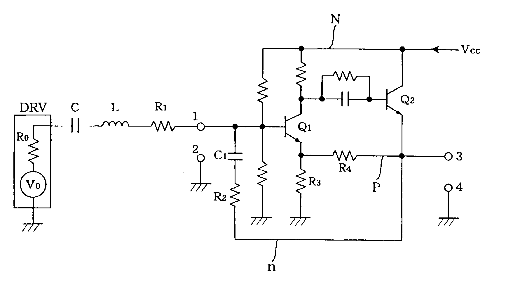
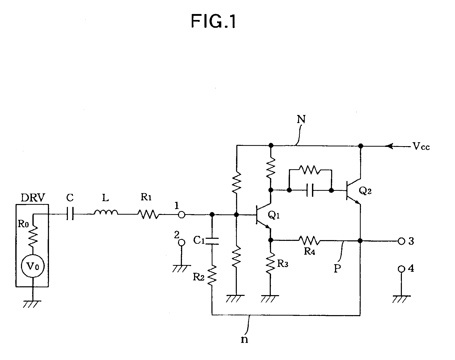
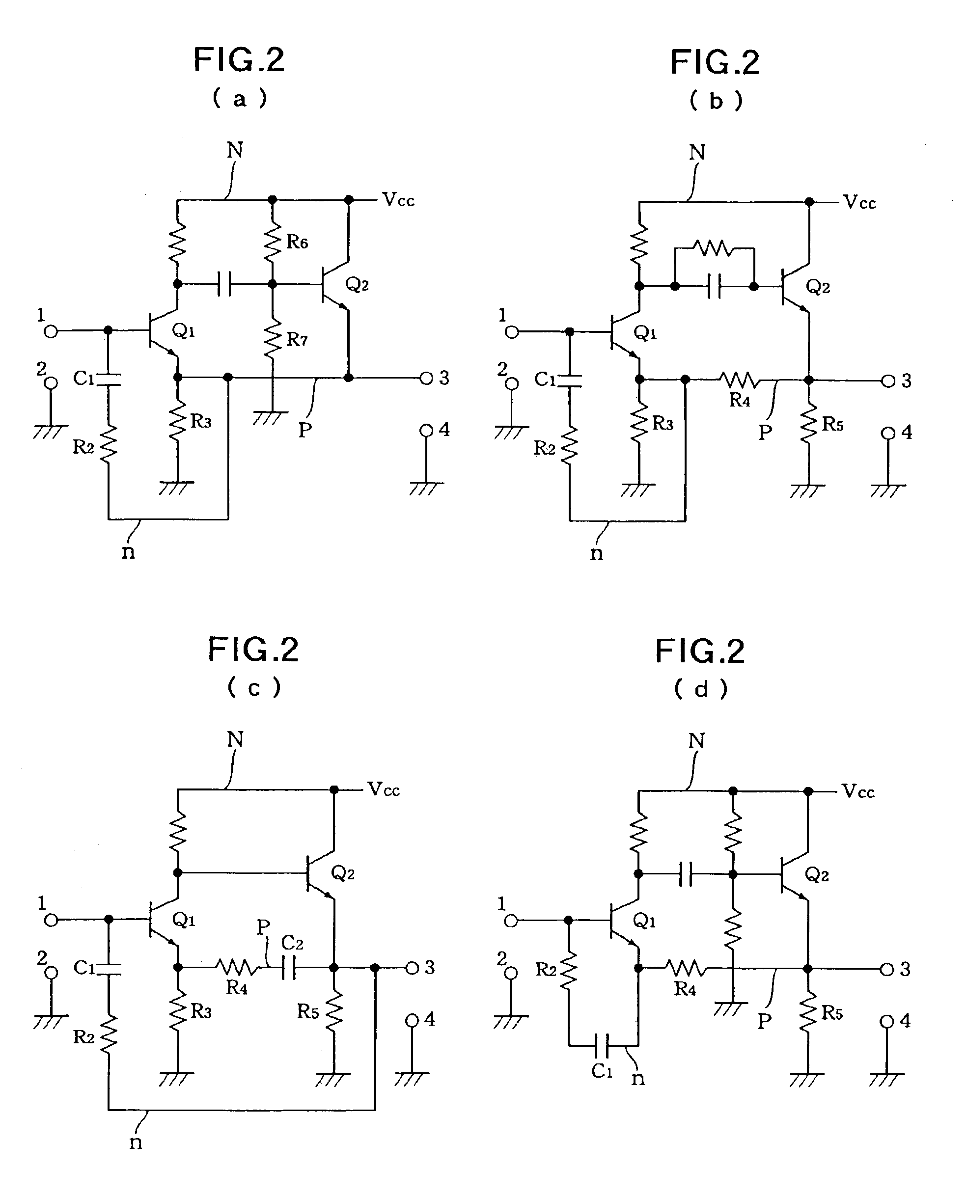
A tuning circuit of the present invention is so constituted that a current component may be taken out by applying an input signal to an end of a series connected circuit consisting of an inductor and a capacitor and earthing the other end thereof through a negative resistance circuit to compensate a series resistance component from the above described reason.

Therefore, if the negative resistance circuit is constituted by a two stage transistor amplifying circuit, the negative resistance circuit requires the following requirements.

That is, since an input terminal of a forward stage circuit thereof (an input terminal of the negative resistance circuit) is connected to a tuning circuit, it is necessary that an input resistance of this circuit becomes a negative resistance. Further, if this circuit is an inverse amplifying circuit, a circuit following to this must be constituted so as to have construction of non-inverse amplification and low impedance output. If a two stage circuit is c...


PUM


Abstract

A tuning circuit using a negative resistance circuit for compensating an equivalent series resistance component thereof is provided. The negative resistance circuit has simple circuit construction and design and adjustment thereof is easy. The tuning circuit comprises a series resonance circuit and a negative resistance circuit connected to the series resonance circuit in series. In the negative resistance circuit, a first transistor constitutes an inverse amplifier by providing a resistor in an emitter circuit thereof and a second transistor constitutes an emitter follower circuit. A positive feedback circuit is constituted by feeding back an output of the emitter follower circuit to an emitter circuit of the first transistor and a negative feedback circuit is constituted by feeding back an output terminal to a base circuit of the first transistor. Thus a negative resistance is produced between this base input terminal and an earth. In this case, since a desired negative resistance value is obtained by adjusting a feedback quantity of both the feedback circuits, Q of the tuning circuit can be set to a desired value.

Description

BACKGROUND OF THE INVENTION1. Field of the InventionThe present invention relates to circuit construction of a tuning circuit to improve frequency selectivity thereof by using a negative resistance circuit.2. Description of the Related ArtAs a method for improving frequency selectivity of a tuning circuit there are methods for improving Q of the tuning circuit by a negative resistance circuit and one of them is a method for compensating equivalent series resistance component of a tuning circuit by constituting it so that an inductor is connected to a capacitor in series and an input signal are applied to one side thereof, and the other side is earthed through a negative resistance circuit. Compensation of the equivalent series resistance component is done to obtain the following two merits. That is, one of them is a merit able to keep a 3 dB band width constant because a value of ωL is changed by changing a tuning frequency but Q changes in proportion to a frequency (Q=ωL / r) since a...

Claims


Application Information

Patent Timeline
IPC IPC(8): H03H11/52H03H11/00H03H7/01H03H11/04H03H11/12H03H7/12H03J3/18
CPCH03H11/52H03H7/12H03H11/1291
Inventor KAWAI, KAZUO
Owner GEN RES OF ELECTRONICS
Learn More