
Electrode-less discharge lamp lighting apparatus, bulb-shaped electrode-less fluorescent lamp, and discharge lamp lighting apparatus

a discharge lamp and lighting apparatus technology, applied in the direction of electric variable regulation, process and machine control, instruments, etc., can solve the problems of user discomfort, difficulty in realizing a fluorescent lamp with a dimming capability whose functional level, electrode-less bulb-shaped fluorescent lamp with a dimming capability has not yet developed, etc., to suppress discontinuous luminous change

Inactive Publication Date: 2005-03-22
PANASONIC CORP
View PDF12 Cites 49 Cited by
  • Summary
  • Abstract
  • Description
  • Claims
  • Application Information

AI Technical Summary

Benefits of technology

With the above construction, the current equal to or larger than the holding current is forcefully applied to the triac for a duration between the turn-on of the triac included in the dimming unit and the generation of the high-frequency current. Moreover, the current is allowed to keep flowing through the triac during the turn-on period of the triac. Therefore, problems occurring to the discharge lamp, such as flicker, caused by the interruption in current flow can be prevented.
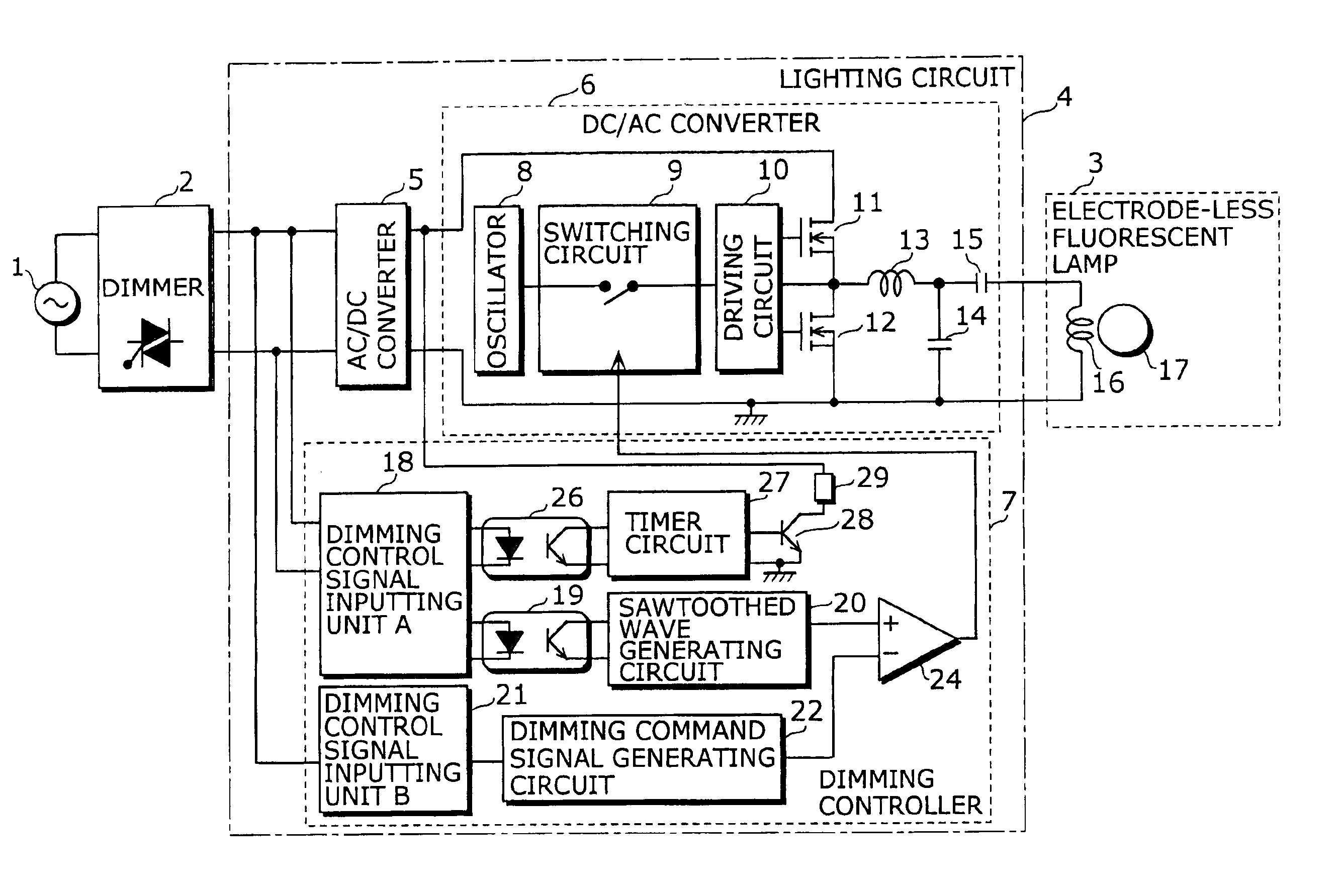
To realize a current drawing circuit as described above, the dimming controlling unit may include: a timer circuit operable to output a signal indicating a period of time that lasts at least the time lag; and a switching element operable to allow a current whose value is at least the threshold to flow across the output terminals of the AC / DC converting unit via a resistor for the period of time indicated by the signal inputted by the timer circuit. In this case, it is preferable that the dimming controlling unit further includes: a dimming control signal inputting circuit operable to output a signal indicating the turn-on of the phase-controlled AC voltage; and a signal transmitting circuit operable to transmit the signal outputted from the dimming control signal inputting circuit to the timer circuit in a state where the signal transmitting circuit is electrically isolated. By doing so, noise can be reduced and the overall operation will be executed with stability.
Furthermore, the dimming controlling unit may further include: a sawtoothed wave signal generating circuit operable to generate one of a sawtoothed wave signal and a triangular wave signal that is synchronized with the timing of the turn-on of the phase-controlled AC voltage; a dimming command signal generating circuit operable to generate a dimming command signal that carries a voltage corresponding to a period of time during which the phase-controlled AC voltage is turned on; and a comparator operable to compare one of the sawtoothed wave signal and the triangular wave signal to the dimming command signal and output the intermittent command signal as a comparison result. In this case, it is preferable that the dimming controlling unit further includes: a dimming control signal inputting circuit operable to output a signal indicating the turn-on of the phase-controlled AC voltage; and a signal transmitting circuit, such as a photo-coupler, operable to transmit the signal outputted from the dimming control signal inputting circuit to the sawtoothed wave signal generating circuit in a state where the signal transmitting circuit is electrically isolated. By doing so, noise can be reduced and the overall operation will be executed with stability.

Problems solved by technology

On the other hand, unlike the bulb, the fluorescent lamp emits light by discharging, and therefore it is difficult to realize a fluorescent lamp with a dimming capability whose functional level is high enough to be practically used.
However, an electrode-less bulb-shaped fluorescent lamp with a dimming capability has not developed so far.
While developing the electrode-less bulb-shaped fluorescent lamp with the dimming capability, the Applicant found the following problems.
When this malfunction happens, flicker and no lights, i.e., discontinuous luminous change may occur to the bulb-shaped discharge lamp, making a user uncomfortable.
However, once having used the incandescent bulb, the user will become sensitive to the discontinuous luminous change of the bulb-shaped electrode-less fluorescent lamp and will experience considerable discomfort.

Method used


Image

  • Electrode-less discharge lamp lighting apparatus, bulb-shaped electrode-less fluorescent lamp, and discharge lamp lighting apparatus
  • Electrode-less discharge lamp lighting apparatus, bulb-shaped electrode-less fluorescent lamp, and discharge lamp lighting apparatus
  • Electrode-less discharge lamp lighting apparatus, bulb-shaped electrode-less fluorescent lamp, and discharge lamp lighting apparatus

Examples


first embodiment

(First Embodiment)

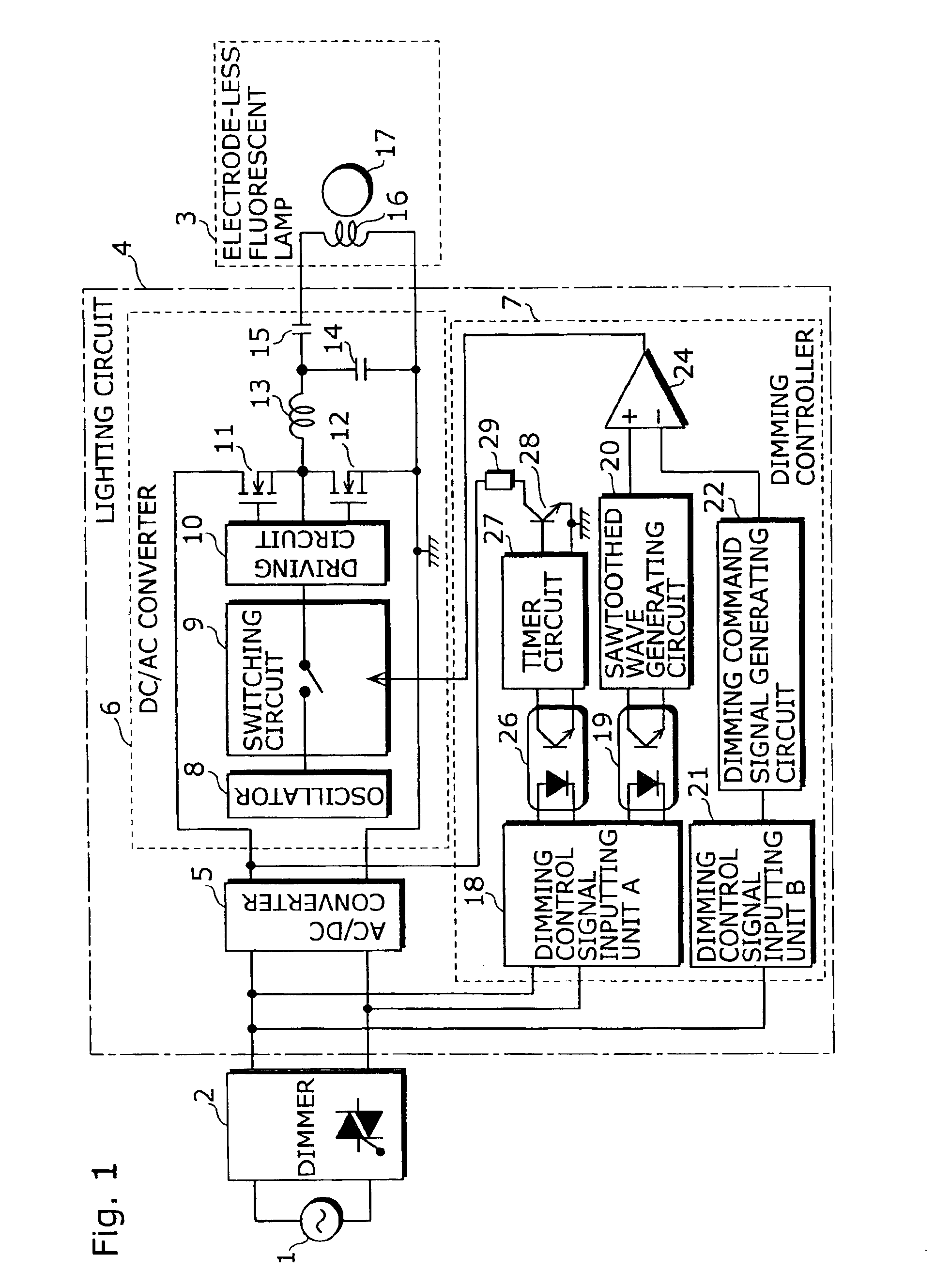
FIG. 1 is a block diagram showing the overall circuit construction of a discharge lamp lighting apparatus of a first embodiment of the present invention. This discharge lamp lighting apparatus is capable of dimming light for an electrode-less fluorescent lamp which is a kind of discharge lamps, and is mainly composed of a lighting circuit 4 and an electrode-less fluorescent lamp 3. In FIG. 1, an AC power 1 and a dimmer 2 are also shown together with the discharge lamp lighting apparatus.

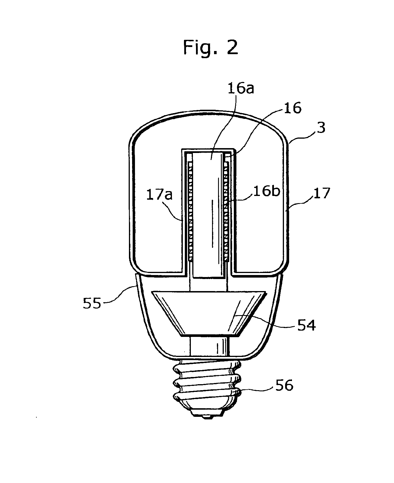
FIG. 2 is a schematic cross-sectional diagram where a bulb-shaped electrode-less fluorescent lamp is realized as one example of the discharge lamp lighting apparatus. As shown, this bulb-shaped electrode-less fluorescent lamp is composed of the electrode-less fluorescent lamp 3, a circuit board 54, and a base 56. Here, the circuit board 54 includes the lighting circuit 4 shown in FIG. 1, and applies a high-frequency voltage to the electrode-less fluorescent lamp 3. To be more specif...

second embodiment

(Second Embodiment)

The following is a description of a discharge lamp lighting apparatus according to a second embodiment of the present invention.

FIG. 9 is a diagram showing the circuit construction of the discharge lamp lighting apparatus of the second embodiment of the present invention. This discharge lamp lighting apparatus is capable of dimming an electrode fluorescent lamp which is a kind of discharge lamps, and is mainly composed of a lighting circuit 4a and an electrode fluorescent lamp 3a. Note that FIG. 9 shows an AC power 1 and a dimmer 2 together with the discharge lamp lighting apparatus.

The discharge lamp lighting apparatus of the present embodiment is different from that of the first embodiment in that a discharge bulb 17b has electrodes. Another difference is that a load resonant circuit is included in the lighting circuit 4a to light up the electrode fluorescent lamp 3a. Therefore, the common components are assigned the same numerals as in the first embodiment and ...


PUM


Abstract

An electrode-less discharge lamp lighting apparatus which is electrically connected to a dimming unit (2) is provided with: an electrode-less fluorescent lamp (3); and a lighting circuit (4) operable to apply a high-frequency voltage to the electrode-less fluorescent lamp (3), wherein the lighting circuit (4) includes: an AC / DC converting unit (5) operable to convert a phase-controlled AC voltage outputted from the dimming unit (2) into a DC voltage; a DC / AC converting unit (6) operable to convert the DC voltage into a high-frequency voltage; and a dimming controlling unit (7) that includes a resistor (29), a switching element (28), and a timer circuit (27) so as to detect a timing of a turn-on of the phase-controlled AC voltage and to, based on the detected timing, allow a current whose value is at least a threshold to flow across output terminals of the AC / DC converting unit (5) for at least a duration of a time lag between the turn-on of the phase-controlled AC voltage and the generation of the high-frequency voltage by the DC / AC converting unit (6).

Description

TECHNICAL FIELDThe present invention relates to a discharge lamp lighting apparatus and an electrode-less discharge lamp lighting apparatus, and in particular to a bulb-shaped electrode-less fluorescent lamp with a dimming capability.BACKGROUND ARTCompared to an incandescent bulb, a fluorescent lamp has higher efficiency and a longer life. On that account, the fluorescent lamp has come into wide use in terms of the global environmental protection and cost effectiveness. In recent years, a bulb-shaped fluorescent lamp with no electrodes has received attention as an economical light source and is now in increasing demand because its life is several-fold longer than a conventional bulb-shape fluorescent lamp with electrodes.Also, a bulb-shaped fluorescent lamp that is designed to include a fluorescent lamp and a lighting circuit in one piece has also received attention as an energy-saving light source used in housing spaces, hotels, restaurants, and so forth. One of the reasons for the...

Claims


Application Information

Patent Timeline
IPC IPC(8): H05B41/39H05B41/282H05B41/28H05B41/392
CPCH05B41/2806H05B41/2828H05B41/3924Y10S315/04Y02B20/22Y02B20/00
Inventor TAKAHASHI, KENICHIROUKOMINAMI, SATOSHIMIYAZAKI, KOUJIKURACHI, TOSHIAKITAKEDA, MAMORUNAGAGATA, NOBUYOSHI
Owner PANASONIC CORP
Learn More