
Segmented photodetectors for detection and compensation of modal dispersion in optical waveguides

a technology of optical waveguides and segmented photodetectors, which is applied in the field of optical fiber systems, can solve the problems of reducing the maximum data transmission rate, limiting bandwidth-distance products of typical multimode fibers, and reducing the total transmission capacity of fibers, so as to improve the distribution of optical modes

Inactive Publication Date: 2005-03-22
GEORGIA TECH RES CORP
View PDF15 Cites 8 Cited by
  • Summary
  • Abstract
  • Description
  • Claims
  • Application Information

AI Technical Summary

Benefits of technology

Another embodiment of the system includes a plurality of detection zones for detecting a plurality of modes of light incident on the plurality of detection zones. The plurality of detection zones are positioned adjacent to one another on a substrate and arranged in a coplanar, non-coplanar, annular or non-annular configuration. An optical element is arranged between the photodetector and an optical fiber to enhance the distribution of optical modes.

Problems solved by technology

Modal dispersion reduces the maximum data transmission rate of the optical communication system and thus diminishes the total transmission capacity of the fiber.
Importantly, the bandwidth-distance products of typical multimode fiber are severely limiting.
Unfortunately, modal dispersion remains the dominant bandwidth limiting mechanism in multimode fibers.
Furthermore, as compared to single mode fibers, these limits reduce the capacity of multimode fiber by orders of magnitude.
Thus, a heretofore unaddressed need exists in the industry to address the aforementioned and / or other deficiencies and / or inadequacies.

Method used


Image

  • Segmented photodetectors for detection and compensation of modal dispersion in optical waveguides
  • Segmented photodetectors for detection and compensation of modal dispersion in optical waveguides
  • Segmented photodetectors for detection and compensation of modal dispersion in optical waveguides

Examples


Embodiment Construction

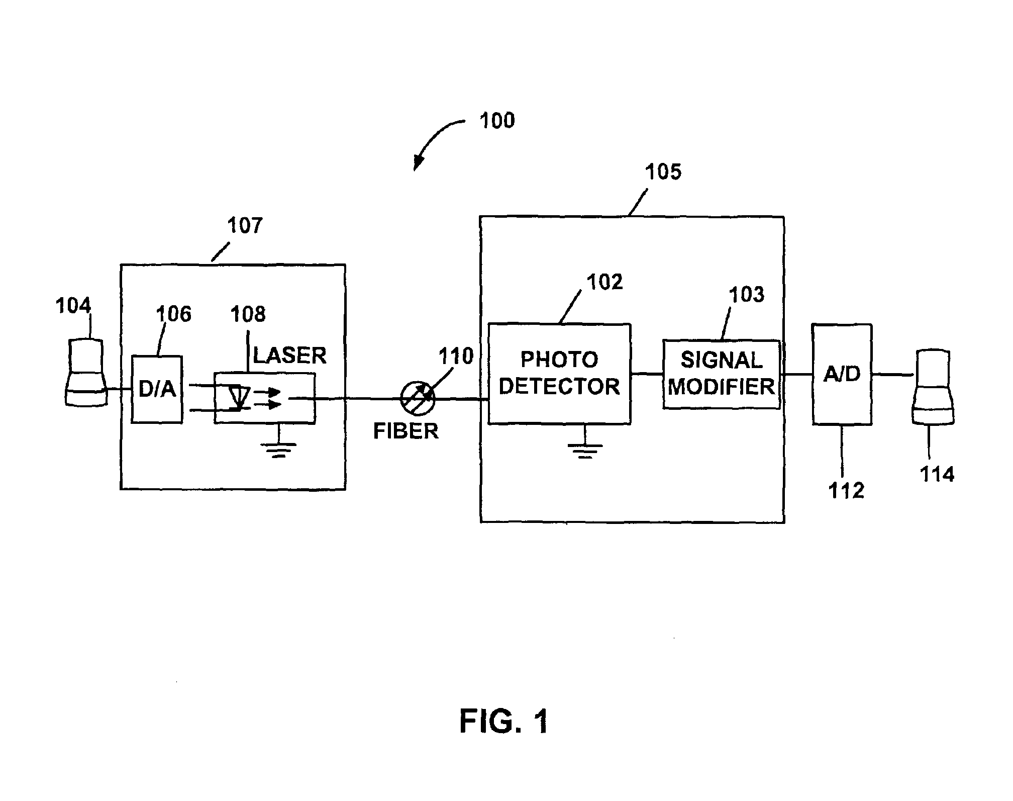
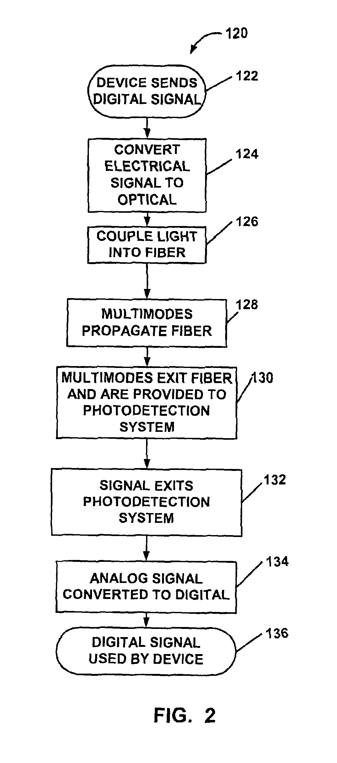
Disclosed herein are methods and systems that involve segmented photodetectors for detection and compensation of modal dispersion in optical waveguides. To facilitate description of the inventive systems and methods, several example devices and methods that can be used to implement the segmented photodetectors are discussed with reference to the figures. Although the systems and methods are described in detail, it will be appreciated that the systems and methods are provided for purposes of illustration only and that various modifications are feasible without departing from the inventive concept. After the example systems have been described, an example of operation of a system will be provided to explain the manner in which the system can be used to provide the method for detection and compensation of modal dispersion in optical communications systems.

Referring now in more detail to the drawings, in which like numerals indicate corresponding parts throughout the several views, FIG....


PUM


Abstract

Systems for detection and compensation of modal dispersion in an optical fiber system including a multisegment photodetector coupled to an end of an optical fiber for detecting optical signals exiting the optical fiber and for converting the optical signals to an electrical output are provided. A representative multisegment photodetector includes a plurality of photodetector regions configured such that each of the plurality of photodetectors detects a portion of the plurality of optical signals exiting the end of the optical fiber and modifies the signal to reduce the affects of modal dispersion. Other systems are also provided.

Description

TECHNICAL FIELDThe present invention is generally related to optical fiber systems and, more particularly, is related to systems and methods for detection and compensation of modal dispersion or differential modal delay in optical waveguides.BACKGROUND OF THE INVENTIONIn an optical communication system deploying a multi-mode fiber, an optical signal launched into the fiber propagates along the fiber as multiple modes, each of which exhibits a different group velocity. A portion of the source optical signal resides in the different modes. The multiple modes can have different arrival times at the end of the fiber. The different group velocities of the modes cause a pulse formed from more than one mode to spread out as it propagates, and is referred to as intermodal dispersion which distorts the optical signal. Intermodal dispersion causes the optical signal initially launched through a fiber at a predetermined frequency and an initial phase to vary as a function of the length of the ...

Claims


Application Information

Patent Timeline
Patent Type & Authority Patents(United States)
IPC IPC(8): G02B6/42H01L31/02G01J1/42H04B10/2581
CPCG01J1/4228G02B6/4202H04B10/2581H01L31/02024G02B6/4206
Inventor RALPH, STEPHEN E.PATEL, KETAN
Owner GEORGIA TECH RES CORP
Learn More