Retrofit fluorescent lamp adaptor

a fluorescent lamp and retrofit technology, applied in the direction of luminescence, coupling device connection, lighting support device, etc., can solve the problem of contributing to being a fire hazard, and achieve the effect of eliminating the potential of receiving electrical shock, convenient installation, and higher wattag

Inactive Publication Date: 2005-03-22
TECHNICAL COSUMER PROD INC
View PDF5 Cites 21 Cited by
  • Summary
  • Abstract
  • Description
  • Claims
  • Application Information

AI Technical Summary

Benefits of technology

Safety being paramount, the lamp adaptor of the present invention, is designed using a housing made of an insulating material such as a rigid injection molded plastic. The boxlike portion of the adaptor housing is comprised of two interlocking pieces, a base and cover, and when assembled is sealed preferably by using thermal bonding or either by using a suitable adhesive or glueing agent, thereby eliminating the potential of a shock hazard.
The use of the “2C” series twin circular fluorescent lamp is preferable for use because it is energy efficient, having a greater illumination output; is more reliable, longer lasting; and is less costly and more readily available in the replacement market.
It is advantageous to use the “2C” twin circular fluorescent lamp as a replacement for the aforementioned “2D” series fluorescent lamp because of its compactness and because of its increased longevity, which typically ranges between 9,000 and 10,000 hours, and because of its reduced operating costs and improved energy efficiency.
It is still yet another object of the present invention to provide for a novel adaptor to retrofit a lighting fixture, such as, a table or a floor lamp that uses a “2D” series fluorescent lamp with a “2C” twin circular fluorescent lamp, where the “2C” series lamp is easily installed by an inexperienced person by snapping the center tube into the receiving ends of the lamp mounting bracket and inserting the plug end into the mating pins located on the “2C” lamp.
An additional object of the present invention to provide for a novel adaptor to retrofit a lighting fixture, such as, a table or a floor lamp that uses a “2D” series fluorescent lamp with a “2C” twin circular fluorescent lamp, is to provide safe operation by interlocking and sealing as a means of being tamperproof to eliminate the potential of receiving an electrical shock.
A final object of the present invention is to provide for a novel adaptor to retrofit a lighting fixture, such as, a table or a floor lamp that uses a “2D” series fluorescent lamp with a “2C” twin circular fluorescent lamp, is to provide non-interchangeability with higher wattage lamps to eliminate the potential of creating a fire hazard.

Problems solved by technology

In addition, lamp wattages greater than the UL approved design wattage rating cannot be used, thereby preventing it to contributing in being a fire hazard.

Method used


Image

  • Retrofit fluorescent lamp adaptor
  • Retrofit fluorescent lamp adaptor
  • Retrofit fluorescent lamp adaptor

Examples


Embodiment Construction

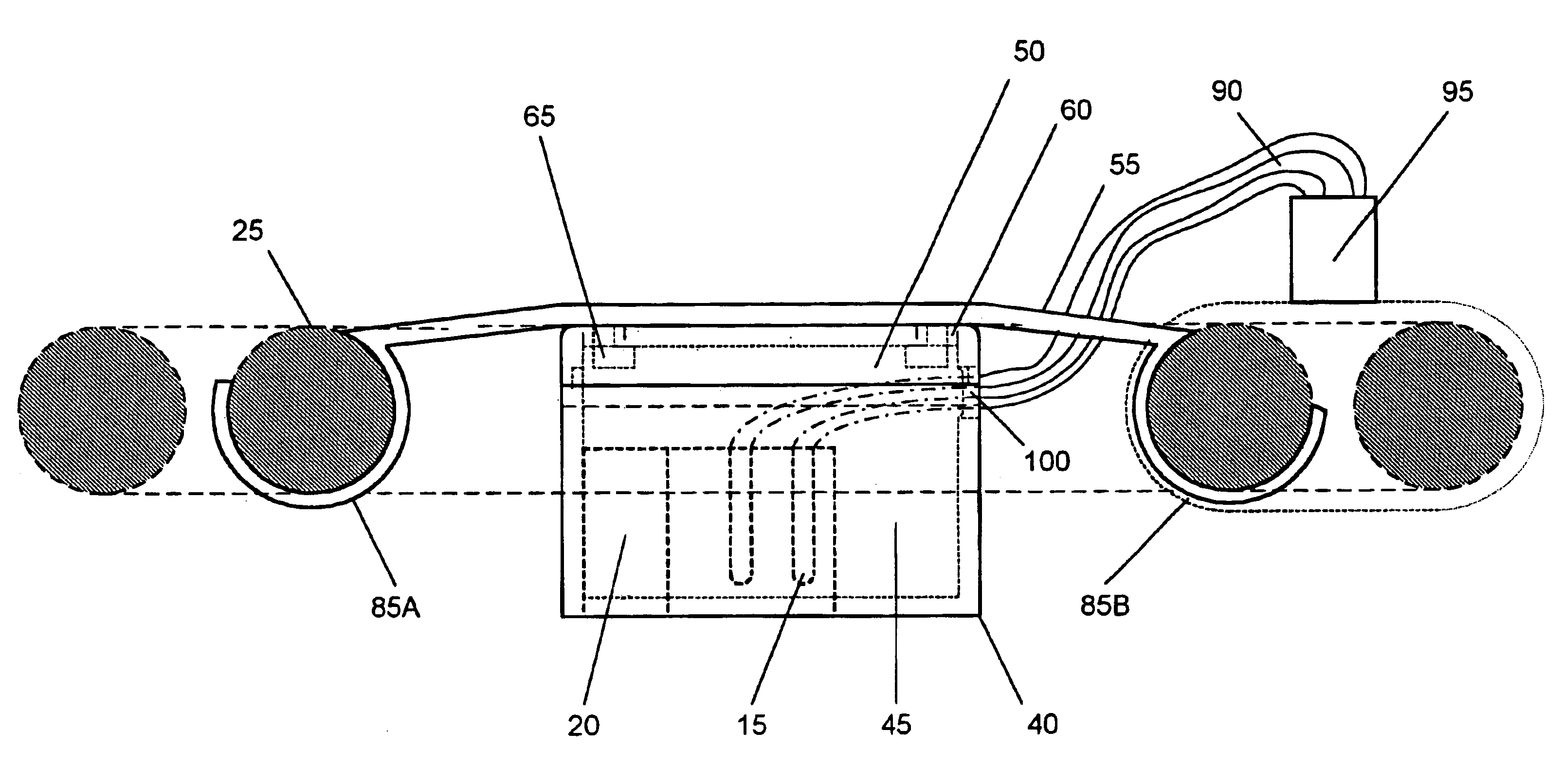
The present invention relates to a novel fluorescent lamp adaptor that will allow the replacement of a “2D” series lamp with a “2C” series twin circular lamp. The adaptor can be easily installed without the need of dismantling an installed fixture or an existing table or floor lamp. Specialized tools are not needed to install the adaptor to convert the fixture from using a type “2D” fluorescent lamp to using a type “2C” twin circular lamp.

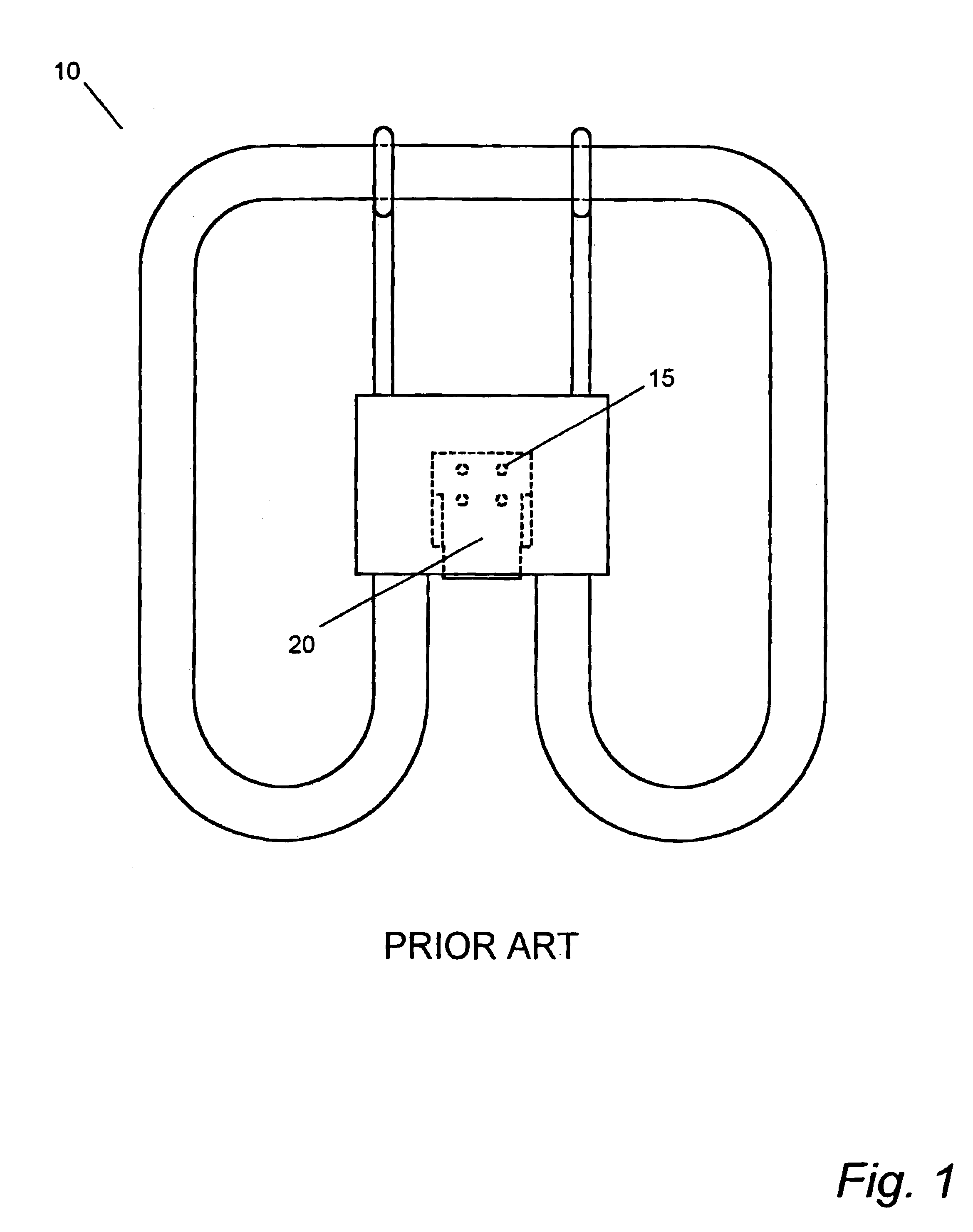
As shown in FIG. 1, the prior art “2D” fluorescent lamp 10 has a 4-pin base configuration for engagement with the lamp receptacle. An array of the four pins 15 that is centrally located in the base recess cavity 20, and where the pins are securely mounted to a base platform.

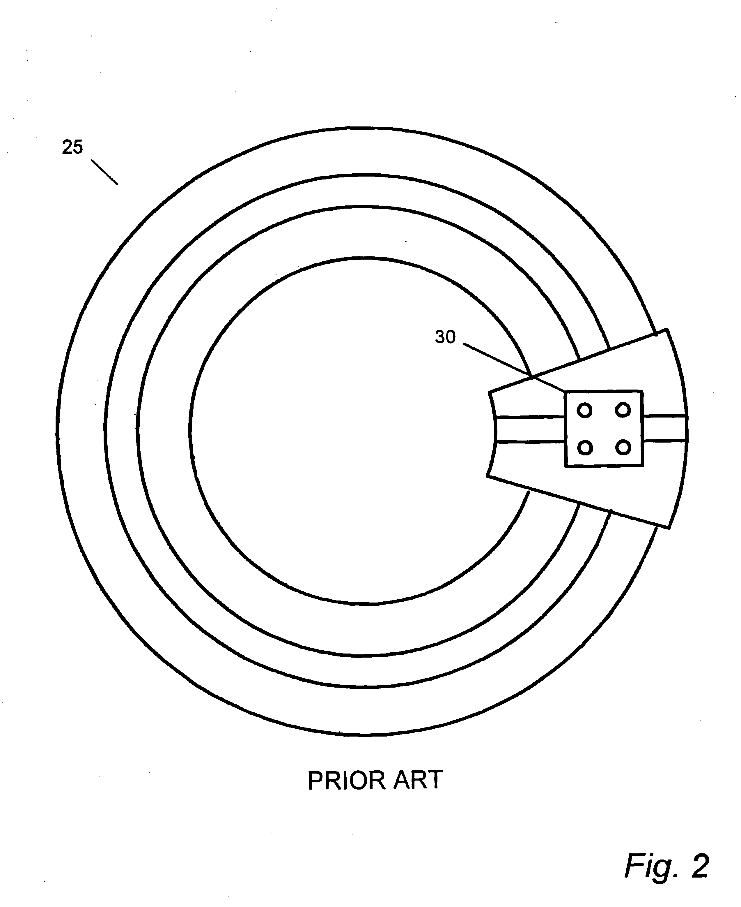
A prior art “2C” twin circular fluorescent lamp 25 is shown in FIG. 2. A centrally located grouping of four-pins 30 comprises the means of interconnecting the lamp to provide power to the lamp. The lamp is commercially available as the TCP Model 17040, which is rated at 40 watts...


PUM


Abstract

A novel fluorescent lamp adaptor that safely converts an existing fluorescent lighting fixture that was designed to hold a “2D” 4-pin series fluorescent lamp to one that uses a “2C” series twin circular fluorescent lamp. The use of a type “2C” fluorescent lamp is advantageous because of its compactness, and greater efficiency, which is commensurate with a longer operational life.

Description

FIELD OF THE INVENTIONThe present invention relates primarily to a fluorescent lamp adaptor, and more particularly, to a fluorescent lamp adaptor which will safely retrofit a fluorescent lamp that is less reliable, with a long life fluorescent lamp, to effect compatibility between the two light sources.BACKGROUND OF THE INVENTIONSome present day fluorescent lighting fixtures use a type “2D” lamp as the source of illumination.Thorn EMI Lighting in the United Kingdom conceived the “2D” fluorescent lamp in 1981. The lamp was so named because it resembles a pair of the letters “D” placed back to back. General Electric Lighting, who introduced several different sizes and wattages to the “2D” style product line, is now manufacturing the lamps. The line was expanded to include five different wattage ratings, ranging from 10 to 38 watts and having three different base styles.Two of the smaller lamps in the series have starters included in the base of the lamp, hence requiring only two pins ...

Claims


Application Information

Patent Timeline
Patent Type & Authority Patents(United States)
IPC IPC(8): F21K2/00F21V19/00H01R33/08H01R33/94
CPCF21V19/0075H01R33/942Y02B20/386H01R33/0809Y02B20/30
Inventor YAN, ELLIS
Owner TECHNICAL COSUMER PROD INC
Why Eureka
Try Eureka