
Reconfigurable WDM mux/demux/OADM

Inactive Publication Date: 2005-03-15
CIENA
View PDF9 Cites 54 Cited by
  • Summary
  • Abstract
  • Description
  • Claims
  • Application Information

AI Technical Summary

Benefits of technology

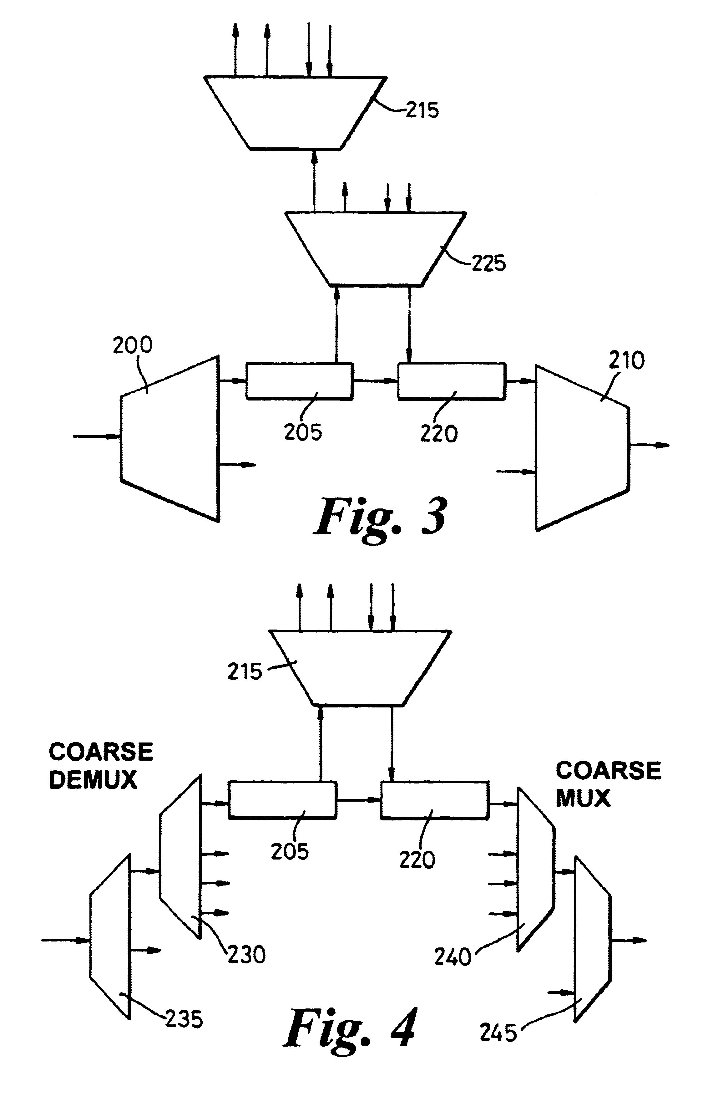
An advantage of such an arrangement is that the choice of which sub bands or wavelengths are added or dropped can be reconfigured remotely, or automatically, with less interruption to pass through sub bands. By switching sub bands rather switching individual wavelengths, the number of switches can be reduced, and consequently optical losses, space requirements and costs can all be reduced. Also, such switching enables easier upgrading from pass through to add drop, of one or more sub bands. Hence initial capital cost of nodes can be reduced, since there is less need to provide redundant add drop capacity initially, since it is relatively easy to add it later. The term “optical switch” is intended to encompass anything which can achieve the function of diverting light from one path to another, and is reconfigurable, either remotely or locally, manually or automatically. This would include optical couplers, mechanical switches, MEMs, liquid crystal devices, or any of the many other technologies which can achieve this.
Similar advantages apply. As a hybrid, it enables devices using different technologies, optimized for each device, to be integrated and thus reduce part count.

Problems solved by technology

This leaves problems of cost and delay involved in sending a worker to a remote site of the node, as well as the space or planning required to allocate space in shelves in the system, required for many such cards in a typical high density approach to the system.
This will require adding additional subband demux cards, which will incur additional cost and footprint to the node as well as the operation of unplugging half band demux cards and reconnecting them to the new cards.
Thus it is difficult or expensive to allow or plan for such upgrade at the time of initial installation, and may cause an undesirable interruption to service of bands being passed through.
Especially in future systems, as there is a possibility for the need to upgrade to provide more amplification of coarse bands, for higher bit rates, which would involve additional planning and space for the scalable nodes, which is often impractical or expensive.

Method used


Image

  • Reconfigurable WDM mux/demux/OADM
  • Reconfigurable WDM mux/demux/OADM
  • Reconfigurable WDM mux/demux/OADM

Examples


Embodiment Construction

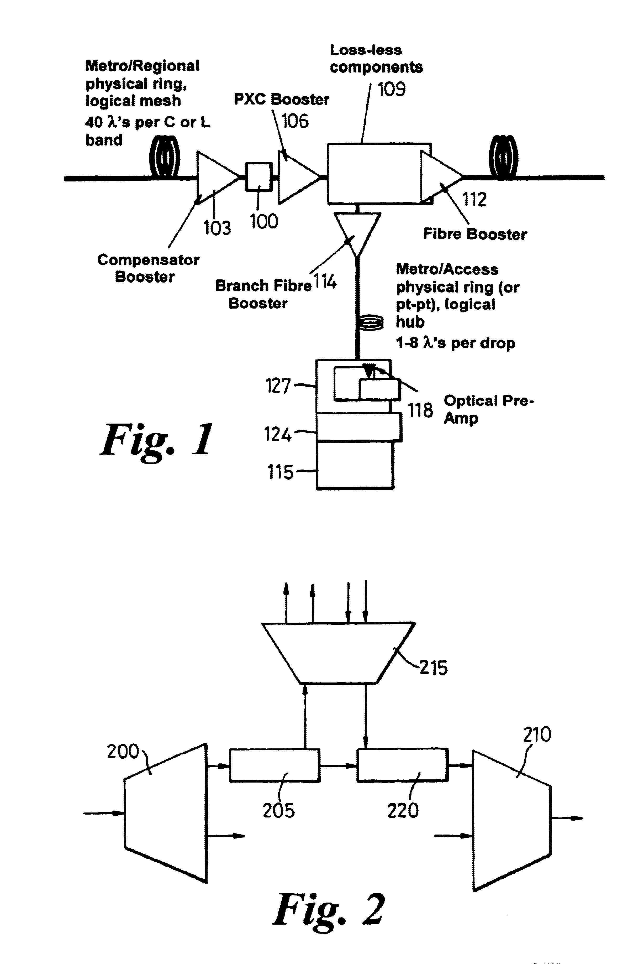
FIG. 1 shows some of the principal features of a node for adding or dropping wavelengths from a high capacity network. In this case the network is a metro or regional network arranged in bidirectional rings, coupled to form a logical mesh. One fiber is shown, though in practice there would be typically 2 or 4, or multiples of 2 or 4. Each carries 32 / 40 wavelengths in one direction in the C band or the L band. A compensator 100 is provided on the input side of the node, if required for dispersion or polarisation mode dispersion compensation across the spectrum. As discussed below, additional compensation can be provided on each sub band, to give finer or more efficient compensation. If required, a compensation booster 103 can be provided before the compensator, to amplify the optical signal. Another booster 106 can be provided before the OADM component 109, to compensate for optical power losses in the OADM component.

A higher power booster 112 is provided on the output side for trans...


PUM


Abstract

A reconfigurable optical add drop module has a coarse demultiplexer, for outputting sub bands of wavelengths, a fine mux / demux, for adding and / or dropping wavelengths, a coarse multiplexer, for remultiplexing the sub bands, an optical switch in between the coarse demultiplexer and the fine mux / demux, to switch the sub bands for pass through, or for add / drop. Reconfiguration can be remote, automatic, with less interruption to traffic. By switching sub bands rather than individual wavelengths, the number of switches can be reduced, and consequently losses, and space requirements can be reduced. Also, upgrading from pass through to add drop, of one or more sub bands is easier. Hence initial capital cost of nodes and the cost of upgrading can be reduced, since there is less need to provide redundant add drop capacity initially. Mid stage access enables external components to be added to the optical path for the sub bands.

Description

FIELD OF THE INVENTIONThis invention relates to reconfigurable optical add drop modules, to components for such modules, to hybrid components, to wafer components, to nodes for optical networks, to methods of operating such networks, and to methods of upgrading such nodes.BACKGROUND TO THE INVENTIONIn conventional optical networks, it is known to use wavelength division multiplexing to transmit multiple data channels along a single fiber. Such networks typically have multiple nodes connected in point to point, ring or mesh configurations. Optical add drop modules (OADM) are used at intermediate nodes in such networks to add or drop wavelengths, and pass through the remaining wavelengths. It has long been desired to provide reconfigurable OADMs to enable remote controlled selection of which wavelengths to add or drop at a particular node, or to control routing of wavelengths between nodes, for example for protection switching purposes. 2×2 optical switches may be provided for switchi...

Claims


Application Information

Patent Timeline
IPC IPC(8): H04B10/213H04J14/02
CPCH04J14/0209H04J14/0213H04J14/0212H04J14/0221
Inventor JOHNSON, PRINCYPEETERS, BRAMWHITEAWAY, JAMES E.
Owner CIENA
Learn More