
Automated positioning of mobile laser peening head

a laser peening head and automatic positioning technology, which is applied in the field of automatic positioning of laser peening heads, can solve the problems of not using automated location verification methods, unable to describe automated location verification methods to be used, and unable to achieve the desired area on the structure. the effect of large area, convenient start-to-finish laser peening processing, and convenient immediate verification

Inactive Publication Date: 2005-03-15
LSP TECH INC
View PDF2 Cites 68 Cited by
  • Summary
  • Abstract
  • Description
  • Claims
  • Application Information

AI Technical Summary

Benefits of technology

An advantage of the present invention is that the system allows the workpiece to remain stationary during processing while permitting laser processing of a potentially large area of that workpiece.
is that the system allows the workpiece to remain stationary during processing while permitting laser processing of a potentially large area of that workpiece.
Another advantage of the present invention is that the system provides a combined sensor and control system that facilitates immediate verification of the proper performance of step (e.g., process head movement, overlay application, laser firing) and permits immediate compensation and / or correction for a step not properly executed initially.
Yet another advantage of the present invention is that the mobile processing unit is configured to carry the overlay application unit(s), laser unit, sensory equipment, and any other related processing / treatment units together, making the mobile processing unit alone able to facilitate start-to-finish laser peening processing of a given location (one to three dimensions) of a given workpiece.
An even further advantage of the present invention is that it is potentially applicable to the treatment of a variety of components including, e.g., aircraft structures (frames, bulkheads, wings, landing gear, fuselages, etc.), large turbine rotors and bearing housings, nuclear waste storage casks, nuclear power systems, large ship components, large power generation components (e.g., land-based turbines, windmill power generation systems, etc.), large cranes and construction equipment, building structures (e.g., girders, beams, and metal bridges).

Problems solved by technology

However, when extending the use of laser peening to very large structures, such as aircraft wing and fuselage components, it is no longer feasible to construct processing cells and machine tools large enough to process the desired areas on these structures.
However, it does not describe automated location verification methods to be used.
Since the operation is carried out under water, there is no automated application of opaque or transparent overlays.
The programmed motion of the head does not address automated real time location verification and correction to a programmed position on a large structure.

Method used


Image

  • Automated positioning of mobile laser peening head
  • Automated positioning of mobile laser peening head
  • Automated positioning of mobile laser peening head

Examples


Embodiment Construction

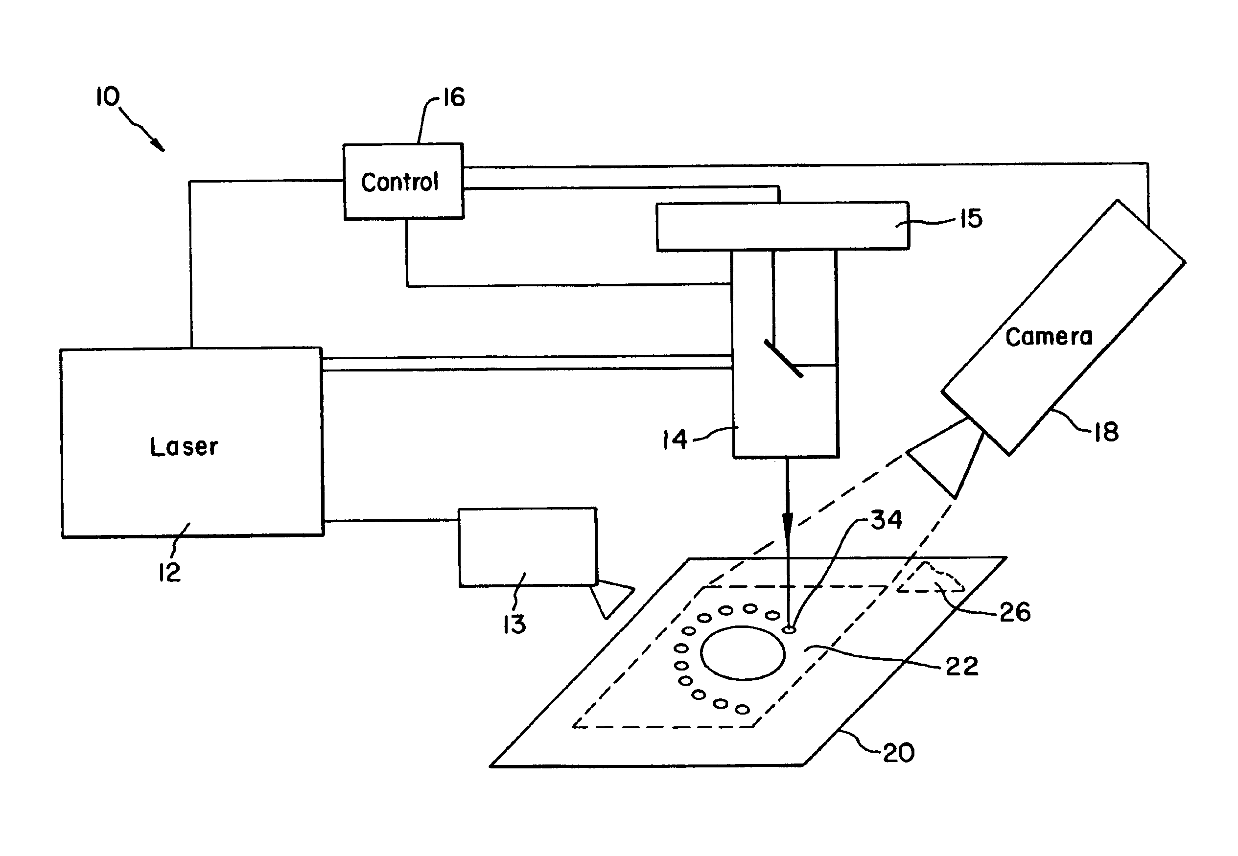
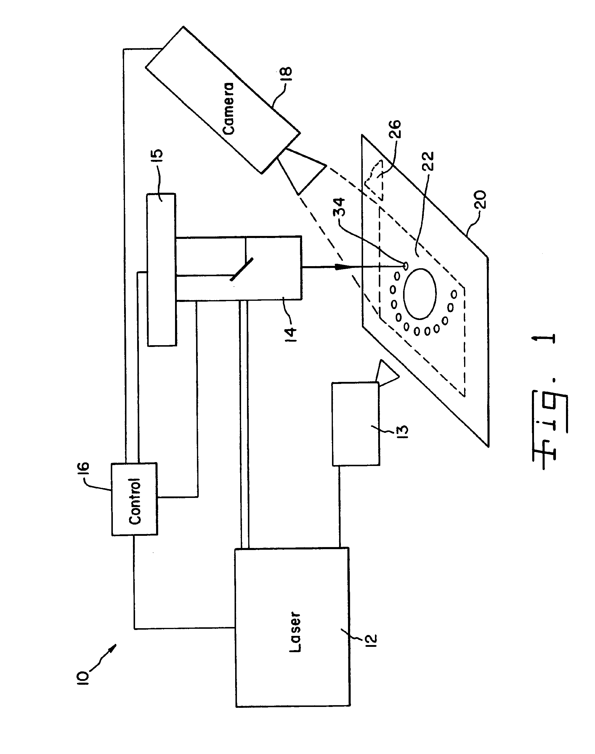
Referring now to the drawings and particularly to FIG. 1, there is shown the laser peening / processing system 10 of the present invention having a laser instrument 12, a laser search peen / process head 14 connected to the laser instrument, and a controller means 16 connected to control the laser instrument 12, laser search peen head 14, overlay applicator mechanism 13, positioning mechanism 15 and inspection instrument 18.

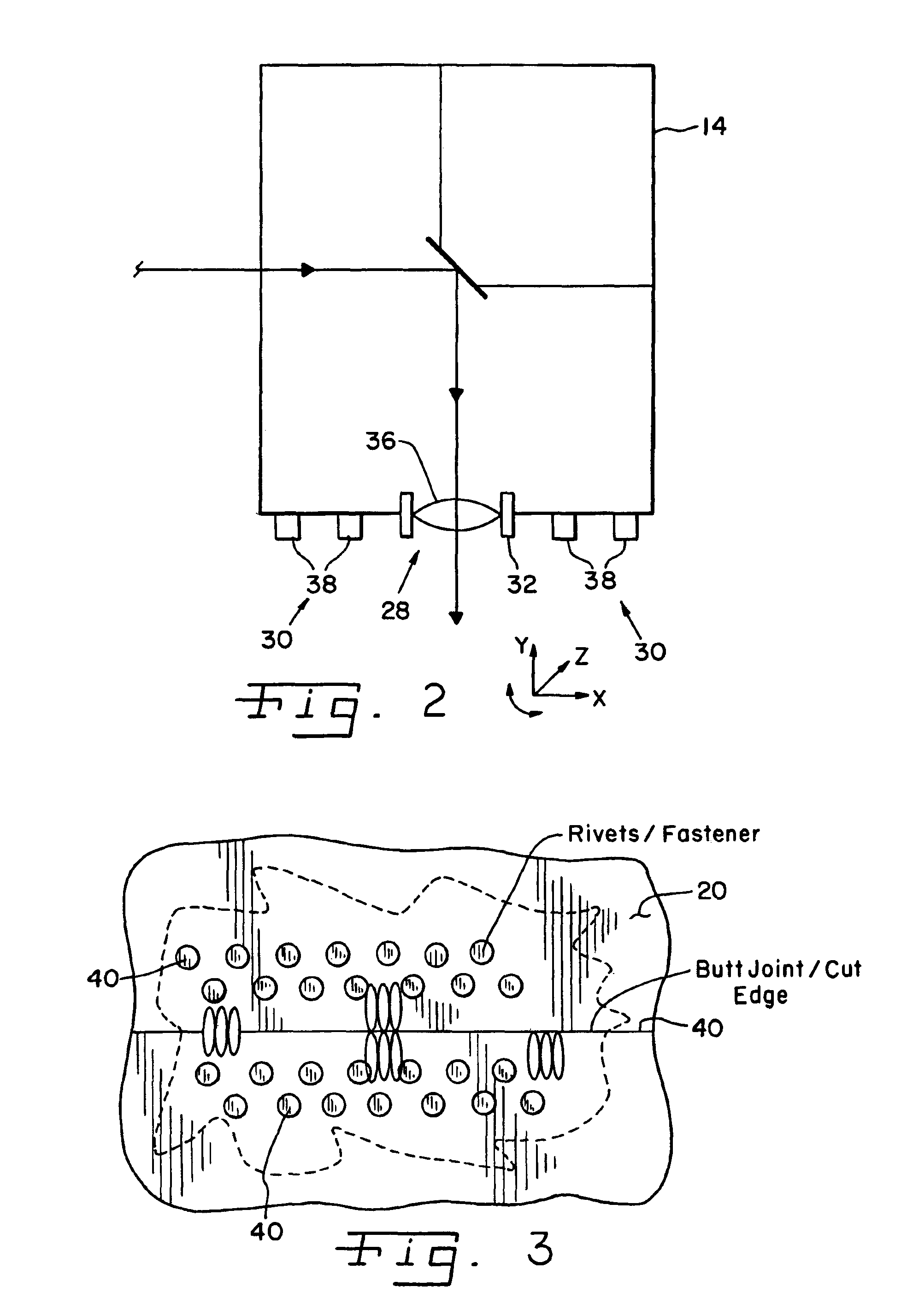
Detection system 10 directs laser search peen head 14 to laser search peen area 22, and during this process, overlay applicator mechanism 13 applies the processing overlay or overlays as sequenced from controller 16, and laser system 12 then delivers a laser pulse to laser search peen head 14. As shown, system 10 is capable of detecting exfoliation corrosion, via camera 18 on significant portions of structure 20 (e.g., aluminum alloy plate section) as well as other surfaces, by examining the laser search peened surface 22 from low magnification to high magnification ...


PUM

PropertyMeasurementUnit
Sizeaaaaaaaaaa
Areaaaaaaaaaaa
Transparencyaaaaaaaaaa

Abstract

The present invention enables the processing head to locate itself precisely on the surface of the structure being processed, and to then reposition itself correctly for the next laser spot. Further, the present invention will complete processing a laser peened area, the area including a multiplicity of spots arranged in a specific pattern, and correctly laser peen each spot in the area under control of a controller including control linkages with the laser.The invention further provides an automated laser peening processing head encompassing spatial position sensing and locating means, as well as programmed spatial positioning, application of overlay materials, verification of proper overlay condition and positioning, and notification of the laser to pulse the surface of the structure.

Description

BACKGROUND OF THE INVENTION1. Field of the InventionThe present invention relates to the automated movement of a laser peening head and particularly to the automated positioning of that mobile laser peening head.2. Description of the Related ArtCurrent laser peening is typically performed within fixed processing cells. The laser is stationary and the beam delivery system, which transfers the laser beams to a processing cell, is also typically stationary. This results in a fixed laser beam position within the processing cell. A workpiece undergoing laser peening must be moved through the path of the fixed laser beams in a pre-programmed positioning sequence to complete laser peening of the part over the prescribed area on the workpiece.This program of sequential positions of the workpiece may include a large number of positioning movements to cover the desired laser peened area with a multiplicity of laser peened spots. Each spot represents one position of the workpiece and one laser...

Claims


Application Information

Patent Timeline
IPC IPC(8): B64F5/00G01N21/88G01N21/95
CPCG01N21/95B64F5/0045B23K26/356B64F5/60C21D7/02
Inventor CLAUER, ALLAN H.DULANEY, JEFF L.LAHRMAN, DAVID F.
Owner LSP TECH INC
Learn More