
Continuously variable transmission system for vehicles

a transmission system and continuously variable technology, applied in mechanical equipment, belts/chains/gearings, belts, etc., can solve the problems of increasing the number of components, increasing the number of system components, and manufacturing costs, and achieving a wide range of transmission ratios and smooth operation.

Inactive Publication Date: 2005-03-15
HONDA MOTOR CO LTD
View PDF6 Cites 38 Cited by
  • Summary
  • Abstract
  • Description
  • Claims
  • Application Information

AI Technical Summary

Benefits of technology

According to this preferred embodiment, in switching from the IVT mode to the direct mode, it is possible to similarly obtain the advantageous effects as described above as to the case of switching from the direct mode to the torque split mode. More specifically, due to the above configuration, by switching from the IVT mode to the direct mode when the transmission ratio of the continuously variable transmission is close to the minimum speed transmission ratio, the switching of the transmission mode can be smoothly carried out such that there is no difference in rotational speed of the third element before and after the switching. Further, it is possible to make use of the continuously variable transmission until the transmission ratio thereof is close to the minimum speed transmission ratio in the IVT mode and start the direct mode when the transmission ratio of the continuously variable transmission is close to the minimum speed transmission ratio. Hence, the continuously variable transmission can be made use of to such an extent that the transmission ratio thereof becomes close to a low-speed side limit of the range (corresponding to the transmission ratio width) of available transmission ratios in both of the IVT mode and the direct mode. Therefore, it is possible to secure a still wider range of transmission ratios of the whole continuously variable transmission system.
as described above as to the case of switching from the direct mode to the torque split mode. More specifically, due to the above configuration, by switching from the IVT mode to the direct mode when the transmission ratio of the continuously variable transmission is close to the minimum speed transmission ratio, the switching of the transmission mode can be smoothly carried out such that there is no difference in rotational speed of the third element before and after the switching. Further, it is possible to make use of the continuously variable transmission until the transmission ratio thereof is close to the minimum speed transmission ratio in the IVT mode and start the direct mode when the transmission ratio of the continuously variable transmission is close to the minimum speed transmission ratio. Hence, the continuously variable transmission can be made use of to such an extent that the transmission ratio thereof becomes close to a low-speed side limit of the range (corresponding to the transmission ratio width) of available transmission ratios in both of the IVT mode and the direct mode. Therefore, it is possible to secure a still wider range of transmission ratios of the whole continuously variable transmission system.
More preferably, the variable transmission system includes a connecting mechanism for connecting the output shaft of the prime mover to the second element of the planetary gear mechanism when a rotational speed of the drive wheels becomes higher than a rotational speed which the drive wheels should have when the toroidal continuously variable transmission is at the maximum speed transmission ratio.
More preferably, the continuously variable transmission system includes a connecting mechanism for connecting the output shaft of the prime mover to the second element of the planetary gear mechanism when a rotational speed of the drive wheels becomes lower than a rotational speed which the drive wheels should have when the toroidal continuously variable transmission is at the minimum speed transmission ratio.
To attain the second object, according to a second aspect of the invention, there is provided a continuously variable transmission system for a vehicle, for transmitting a driving force from a prime mover to drive wheels at a continuously variable transmission ratio,

Problems solved by technology

This increases the number of component parts of the system and manufacturing costs, and makes it impossible to design the system compact in size.
To implement the reverse mode, a brake for reverse travel is necessitated, which further increases the number of component parts and makes the system complicated in construction.
In the conventional continuously variable transmission system described above, however, the angle of tilting of the power rollers are restricted by causing the receiving portions of each trunnion to mechanically abut against the associated stoppers of the upper link, so that a large impact force acts on the upper link.
Further, it is difficult to cause a plurality of trunnions to abut against stoppers simultaneously and uniformly due to variations in the machining accuracy, rigidity, assembling accuracy of component parts, which causes only one trunnion to be brought into abutment with the associated stopper.
In such a case, an excessively larger force is concentratedly applied to the portion of the upper link supporting the trunnion.
Further, variations in torque transmitted by each power roller cause slippage of the power rollers, and the slippage causes abnormal generation of heat, early abrasion due to the heat, and the resulting degradation of durability.
These inconveniences actually make it impossible to positively set the whole region of transmission ratios available from the continuously variable transmission to the range of transmission ratios for actual use, even if the stoppers are provided.

Method used


Image

  • Continuously variable transmission system for vehicles
  • Continuously variable transmission system for vehicles
  • Continuously variable transmission system for vehicles

Examples


Embodiment Construction

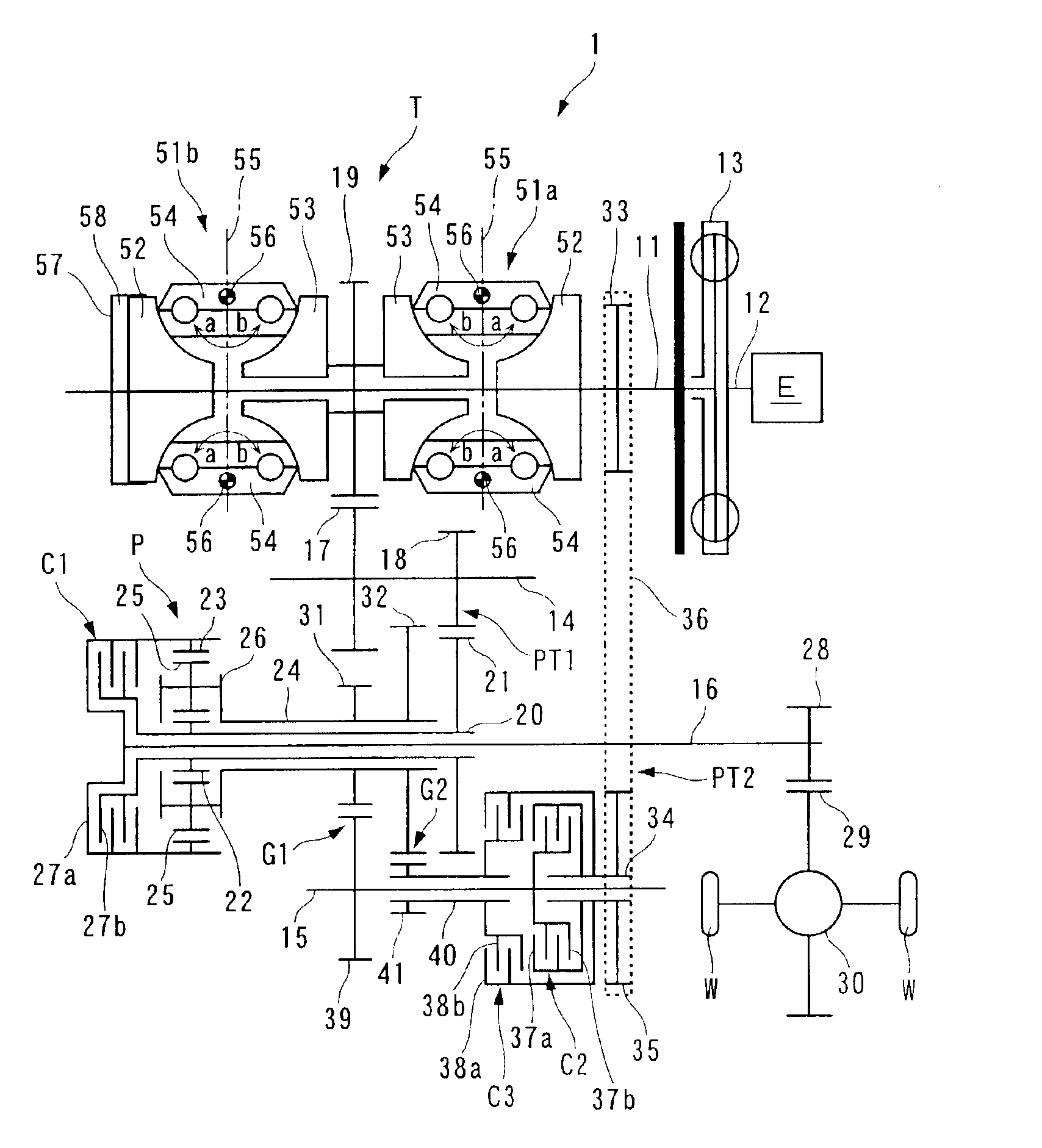
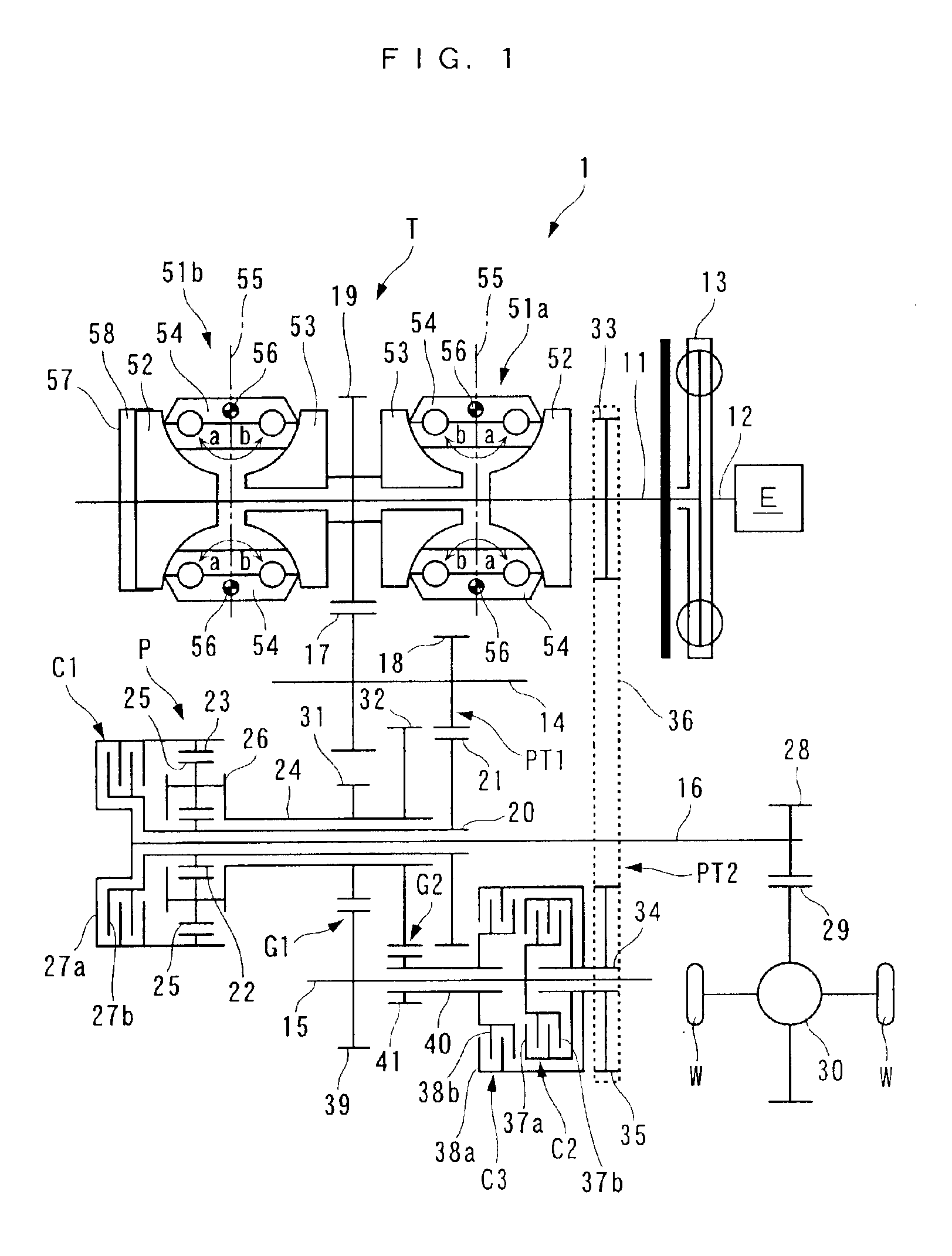
The invention will now be described in detail with reference to the drawings showing preferred embodiments thereof. Referring first to FIG. 1, there is schematically shown a continuously variable transmission system for an automotive vehicle, according to a first embodiment of the invention. The continuously variable transmission system 1 includes a toroidal continuously variable transmission T, a single pinion-type planetary gear mechanism P, a direct clutch C1 (hereinafter referred to as “the first clutch C1”, a torque split clutch C2 (hereinafter referred to as “the second clutch C2”, and an IVT clutch C3 (hereinafter referred to as “the third clutch C3”. Each of the first to third clutches C1 to C3 is formed e.g. by a wet-type multiple disc hydraulic clutch, whose engagement and disengagement is controlled by a hydraulic control circuit, not shown.

The continuously variable transmission T has an input shaft 11 connected to a crankshaft 12 (output shaft) of an internal combustion ...


PUM


Abstract

A continuously variable transmission system designable compact in size and manufacturable at a reduced cost by reducing the number of component parts and securing a maximum transmission ratio width. A toroidal continuously variable transmission has an input member connected to an output shaft of a prime mover, and an output member for outputting rotation of the input member at a continuously variable transmission ratio. A planetary gear mechanism has a first element connected to the output member, a second element connected to drive wheels, and a third element. A first clutch establishes and releases connection between the first element and the second element. A first gear train and a second gear train having a larger gear ratio, are arranged between the output shaft and the third element in parallel. Second and third clutches establish and release respective connections of first and second gear trains.

Description

BACKGROUND OF THE INVENTION1. Field of the InventionThis invention relates to a continuously variable transmission system for vehicles, which is constructed by combining a toroidal continuously variable transmission and a planetary gear mechanism.2. Description of the Prior ArtConventionally, a continuously variable transmission system for vehicles, of the above-mentioned kind, is disclosed e.g. in the publication of Japanese Patent No. 2778038. This continuously variable transmission system includes a toroidal continuously variable transmission, and first and second planetary gear mechanisms. The toroidal continuously variable transmission has an input shaft connected to an engine, and an output shaft connected to sun gears of the first and second planetary gear mechanisms. The first planetary gear mechanism has a planet carrier provided with a first clutch for connecting the planet carrier to a fixing member, and a ring gear connected to an output shaft of the continuously variabl...

Claims


Application Information

Patent Timeline
Patent Type & Authority Patents(United States)
IPC IPC(8): F16H37/06F16H37/08
CPCF16H37/086F16H2037/0886
Inventor OOYAMA, KAZUO
Owner HONDA MOTOR CO LTD
Learn More