
Low profile fluid quick connector

Inactive Publication Date: 2005-03-15
COOPER STANDARD AUTOMATIVE INC
View PDF19 Cites 19 Cited by
  • Summary
  • Abstract
  • Description
  • Claims
  • Application Information

AI Technical Summary

Benefits of technology

The present invention is a low profile fluid quick connector which has a reduced axial length as compared to previously devised fluid quick connectors while still maintaining all of the required quick connector features of full insertion capability and high pull-out force resistance.
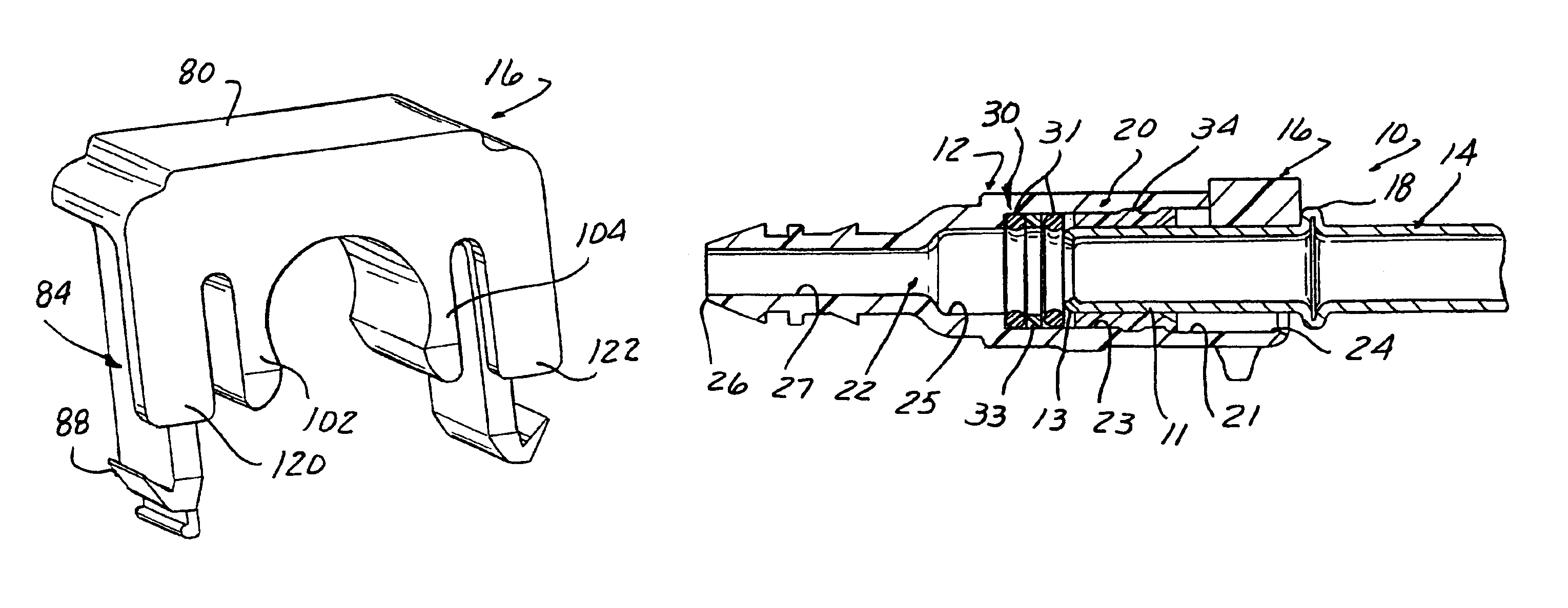
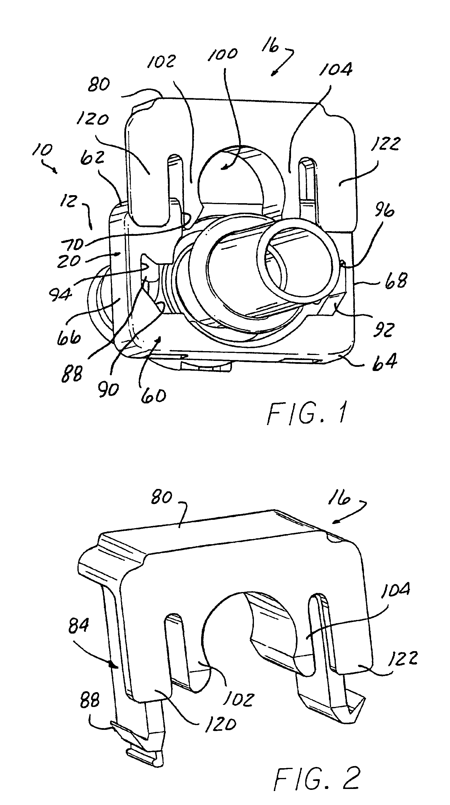
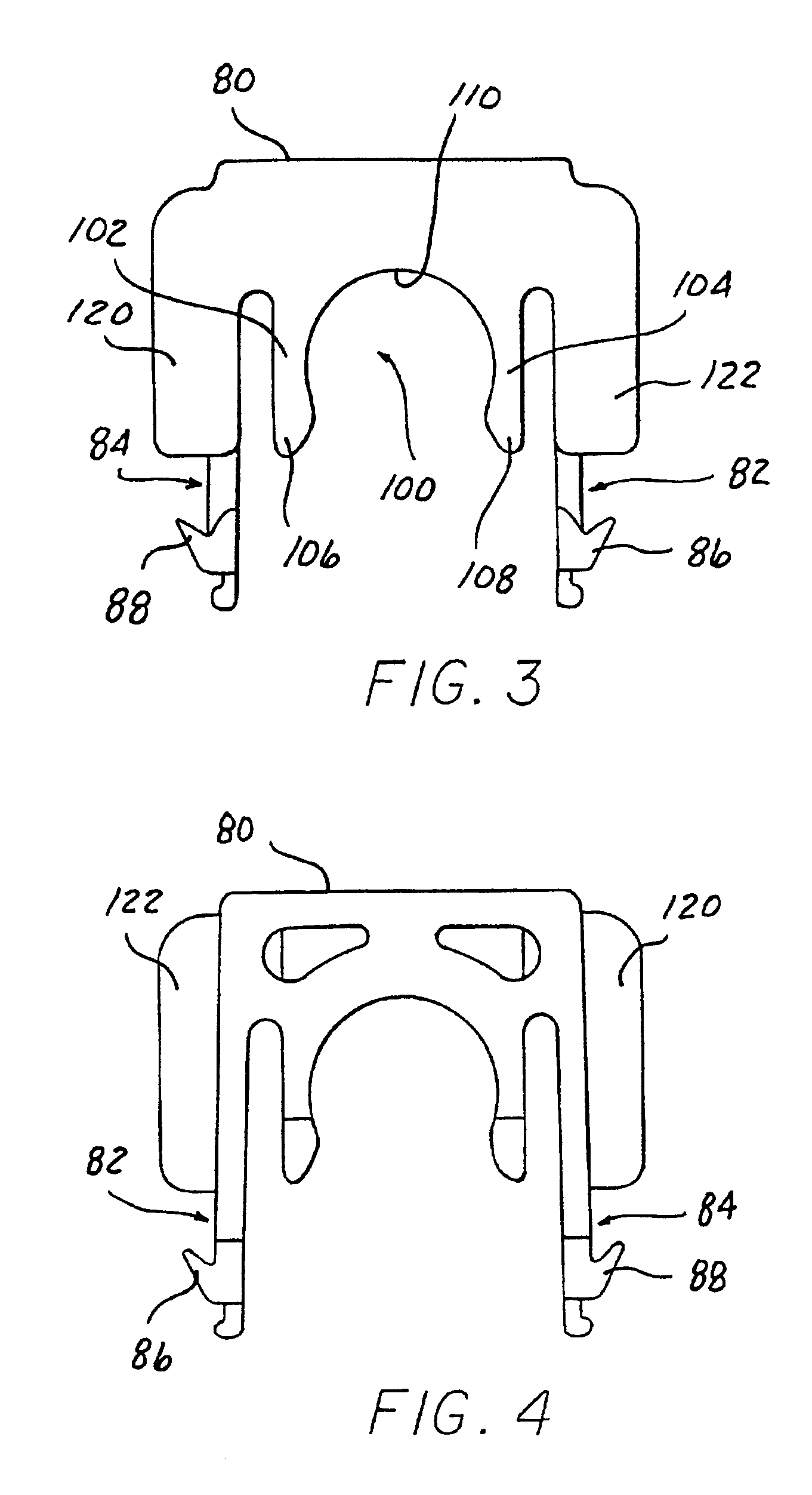
In one aspect of the invention, at least one flange is carried on the retainer and slidingly engagable with the housing when the retainer is coupled to the housing. The at least one flange, which in another aspect of the invention is two laterally spaced flanges, is engagable with an exterior surface of the housing to position the first and second arms on the retainer in an axial position with respect to the housing to prevent contact between a seal member mounted within the bore in the housing and a tip end of the endform in the event that the retainer is in the fully latched position prior to insertion of the endform into the bore in the housing. This non-seal insertion blocking feature is provided with a minimal axial overall length of the retainer which reduces the overall length of the housing to facilitate use of the present connector in restricted space applications.
The fluid quick connector of the present invention provides all of the requirements of a fluid quick connector in so far as providing full insertion capability of an endform into the bore in the housing of the quick connector while preventing contact between the endform and the seals mounted within the bore in the housing if the retainer in the fully latched position in the housing prior to insertion of the endform into the bore in the housing. This prevents a false seal indication for the quick connect. At the same time, the fluid quick connector of the present invention has a reduced axial length thereby facilitating its use in applications having restricted space.

Problems solved by technology

These features have not been able to be provided in a short length quick connect suitable usable in applications having limited space.

Method used


Image

  • Low profile fluid quick connector
  • Low profile fluid quick connector
  • Low profile fluid quick connector

Examples


Embodiment Construction

Referring to FIGS. 1-11 of the drawing, there is depicted a fluid quick connector 10 suitable for interconnecting two fluid operative elements, such as conduits, tubes, as well as endforms carried on fluid operative devices, such as pumps, fuel filters, valves, valve manifolds, etc.

Thus, the quick connector 10 of the present invention, in the following example, will be incorporated in a first component 12 and a second component 14 which are sealingly joinable and held in a sealed, locked position by a retainer means 16. Each of the first and second components 12 and 14, as described above, may be formed as the end portion or endform of a fluid operative device, such as a conduit, pump, fuel filter, etc., or as separate elements each of which receives and is fluidically coupled to a fluid operative device, such as a conduit by means of conduit retention barbs, etc.

The particular shape of the endform of the first and second components 12 and 14 can be integrally formed on the end of a...


PUM


Abstract

A fluid quick connector sealingly latches first and second components, one of which has a through bore and the other has a raised bead spaced from a tip end. A retainer is mountable through a transverse bore in one end of the first component and latched to the first component by projections carried on a pair of legs. A flange on the retainer is positioned to engage a surface of the first component to position the retainer on the first component. Inner disposed arms on the retainer engage a constant diameter portion of the second component and resist movement of the raised bead into or out of the bore in the housing when the retainer is in a fully latched position. The flange on the retainer is spaced from the legs of the retainer to enable the legs to be of minimal thickness for a reduced axial length for the retainer.

Description

BACKGROUNDThe present invention relates, in general, to fluid quick connectors which couple male and female connector components.Snap-fit or quick connectors are employed in a wide range of applications, particularly, for joining fluid carrying conduits in automotive and industrial application. Such quick connectors utilize retainers or locking elements for securing a male connector component, such as a tubular conduit, within a complimentary bore of a female connector component or housing. Such retainers are typically of either the axially-displaceable or radially-displaceable type. The terms “axially-displaceable” or “radially-displaceable” are taken relative to the axial bore through the female component.In a typical quick connector with an axially displaceable, retainer, the retainer is mounted within a bore in a housing of the female connector component of housing. The retainer has a plurality of radially and angularly extending legs which extend inwardly toward the axial cente...

Claims


Application Information

Patent Timeline
IPC IPC(8): F16L37/00F16L37/14
CPCF16L37/144Y10S285/921F16L2201/10
Inventor SZABO, GEORGETHOMAS, ANTHONY
Owner COOPER STANDARD AUTOMATIVE INC
Learn More