
Firing mechanism for paintball gun

Inactive Publication Date: 2010-01-21
LAI BAO SHYAN
View PDF17 Cites 9 Cited by
  • Summary
  • Abstract
  • Description
  • Claims
  • Application Information

AI Technical Summary

Benefits of technology

[0014]The primary object of the present invention is to provide a paintball gun wherein the pressurized air for activating the inner part and the control member comes from the same storage space so that the paintball gun can be a compact paintball gun. No complicated paths or valves are needed and a simple switch member is used to switch the inner part and the control member.
[0015]Another object of the present invention is to provide a paintball gun wherein the air located around the inner part is sent back to the storage space by the second push surface of the flange of the inner part when the inner part is moved forward. The air can be saved and increases the number shoots.
[0016]Yet another object of the present invention is to provide a paintball gun wherein the control member is supported by the inner periphery of the second section and the guide protrusion of the control member is supported by the inner part so that the control member can precisely seal the conjunction opening.
[0017]The control member also supports the movement of the inner part so as to reduce the axial length of the barrel.

Problems solved by technology

Therefore, a high cost is needed.
This causes that the air storage space 83 cannot be well sealed

Method used


Image

  • Firing mechanism for paintball gun
  • Firing mechanism for paintball gun
  • Firing mechanism for paintball gun

Examples


Embodiment Construction

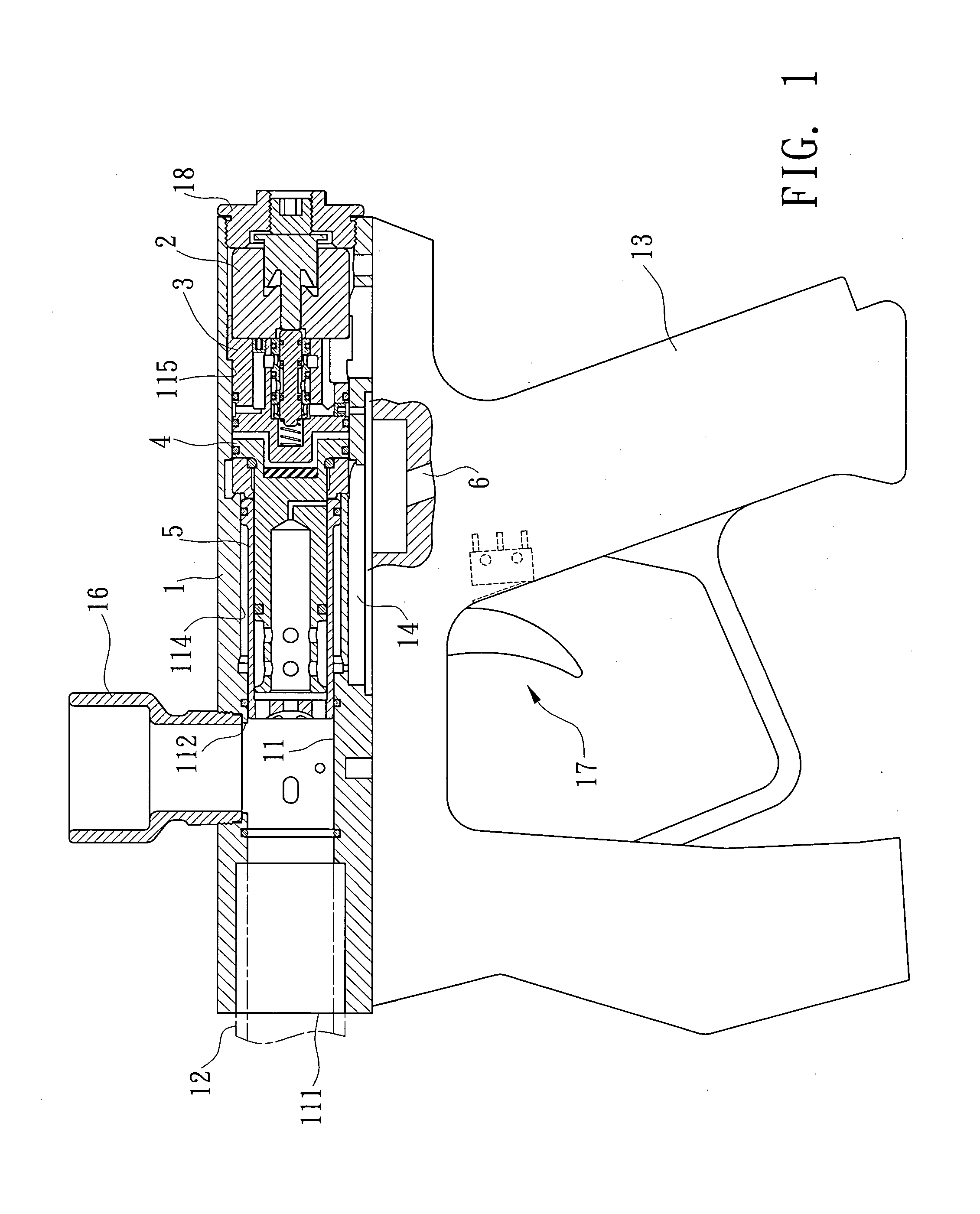
[0026]Referring to FIGS. 1 to 3, the paintball gun of the present invention comprises a barrel 1 having an axial path 11 defined therein and the path 11 includes a closed end and an opening 111 in the other end. A bore 12 is connected with the opening 111. An end cap 18 is connected to the barrel 1 and seals the closed end of the path 11. A paintball inlet 112 communicates with the path 11 and a drop tube 16 is connected to the paintball inlet 112 and paintballs “A” enters the bath 11 via the drop tube 16 and the paintball inlet 112. A first section 114 and a second section 115 are defined in the path 11 and located opposite to the opening 111. The second section 115 has an inner diameter larger than that of the first section 114. A firing mechanism is located in the first and second sections 114, 115 so as to shoot the paintballs “A” in the path 11. A conjunction opening 113 is defined in the conjunction portion between the first and second sections 114, 115. A stop shoulder 116 is...


PUM


Abstract

A firing mechanism for a paintball gun is received in the path of the barrel and a trigger is used to activate the firing mechanism. The firing mechanism includes a driving member, a switch member, a control member and an inner part, all of which are received in the path of the barrel. The driving member drives the switch member to change the air flow in the marker so as to move the control member axially to control the high pressurized air to move the inner part such that the high pressurized air is released to eject the paintballs out from the barrel.

Description

CROSS-REFERENCE TO RELATED APPLICATION[0001]The application is a Continuation-In-Part of Ser. No. 11 / 483,620, filed on Jul. 11, 2006, and entitled “SHOOTING STRUCTURE OF A PAINT BULLET GUN”, now pendingFIELD OF THE INVENTION[0002]The present invention relates to a firing mechanism for a paintball gun and the inner part and the firing mechanism are activated by the same pressurized air source.BACKGROUND OF THE INVENTION[0003]There are two types of firing mechanism for paintball guns and one of which uses mechanical way to fire the paintballs and the other uses electric way to fire the paintballs. The markers include an inner part which his moved axially in the barrel to open and close the paintball inlet and a firing mechanism is used to activate a valve to introduce pressurized air into the barrel to shoot the paintballs.[0004]A conventional paintball gun 90 is shown in FIG. 7, and generally includes a barrel 9 and a handle 8, the barrel 9 includes an action space and a bore 92 whic...

Claims


Application Information

Patent Timeline
IPC IPC(8): F41B11/00
CPCF41B11/721
Inventor LAI, BAO SHYAN
Owner LAI BAO SHYAN
Learn More