
Dual drive pump with dual chain and roller clutch and method

Inactive Publication Date: 2006-03-16
GM GLOBAL TECH OPERATIONS LLC
View PDF11 Cites 13 Cited by
  • Summary
  • Abstract
  • Description
  • Claims
  • Application Information

AI Technical Summary

Benefits of technology

[0005] The pumping system of the present invention is a dually-powered pump with dual chains and a roller clutch. The system provides fluid pressure in a transmission system of a vehicle powerable by more than one power source, such as a gasoline / electric hybrid. The pump is adapted to receive power from either a mechanical power source, such as the vehicle's engine (which may be an internal combustion engine), or an electrical power source, which may be an electric motor or battery, depending upon whether the vehicle is being powered mechanically or electrically. The pump is functionally connected to both the mechanical power source and the electrical power source by chains or the like. A roller clutch provides that only one of the connections between the pump and the mechanical power source or electrical power source is functional at any time and only one of the mechanical power source or electrical power source may drive the pump at any time. Such a pumping system requires only one pump for vehicles powerable by multiple energy sources. The dual chains provide that the pump may be situated off-axis, as may be more convenient for packaging purposes and may reduce transmission axial length. Thus, a pump or a method of pumping utilizing an input connection such as a chain permits the electric motor to be housed non-coaxial with the center axis to improve packaging.

Problems solved by technology

In these previous systems, there is no mechanical ability to run the hydraulic pump when the engine is not running.
However, situations exist where the engine is off but vehicle mechanisms are in motion, such as when a battery powers an electric / gasoline hybrid vehicle.
This solution, however, requires more packaging space than a conventional one-pump system because of the additional pump or pumps required.

Method used


Image

  • Dual drive pump with dual chain and roller clutch and method
  • Dual drive pump with dual chain and roller clutch and method
  • Dual drive pump with dual chain and roller clutch and method

Examples


Embodiment Construction

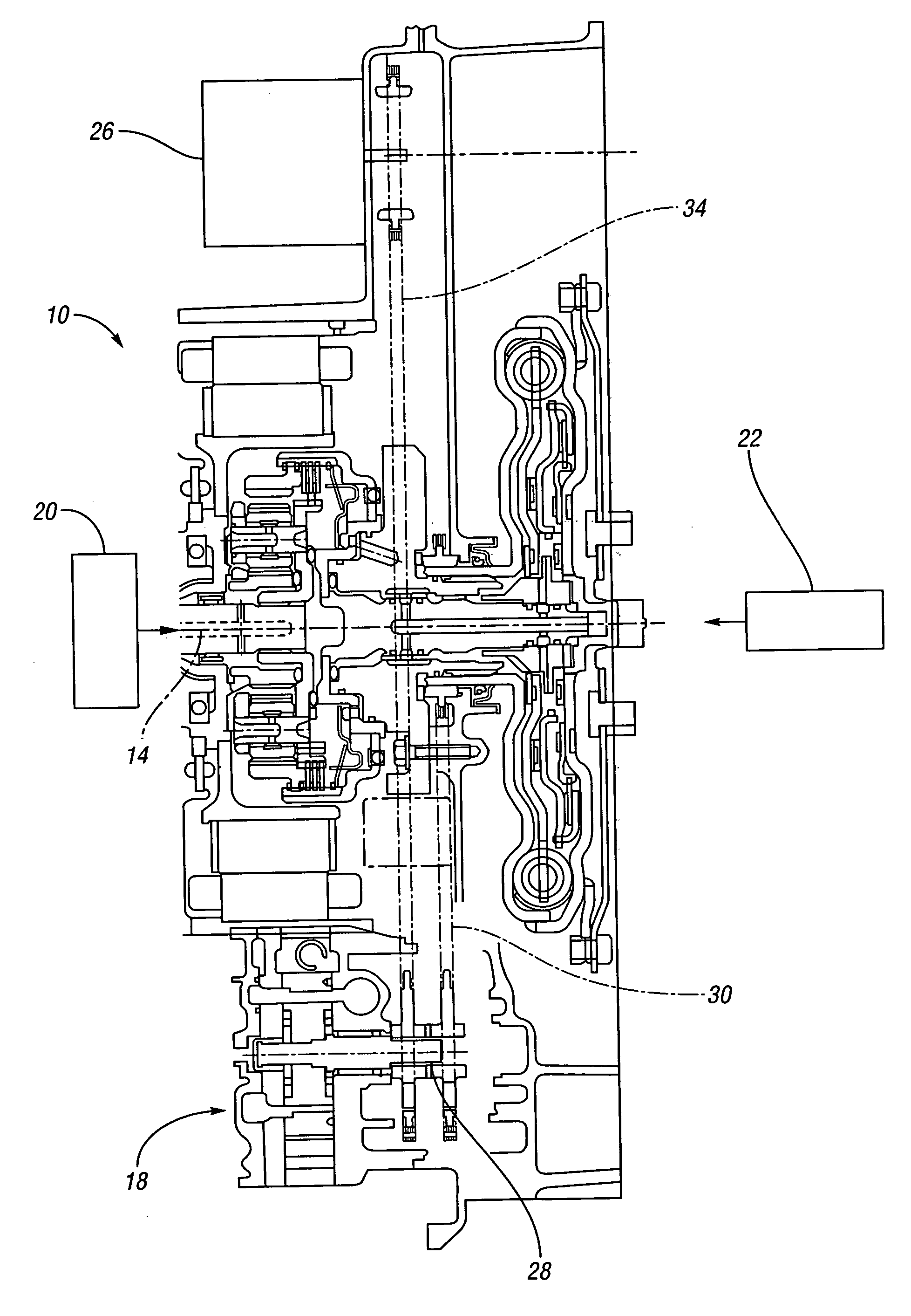
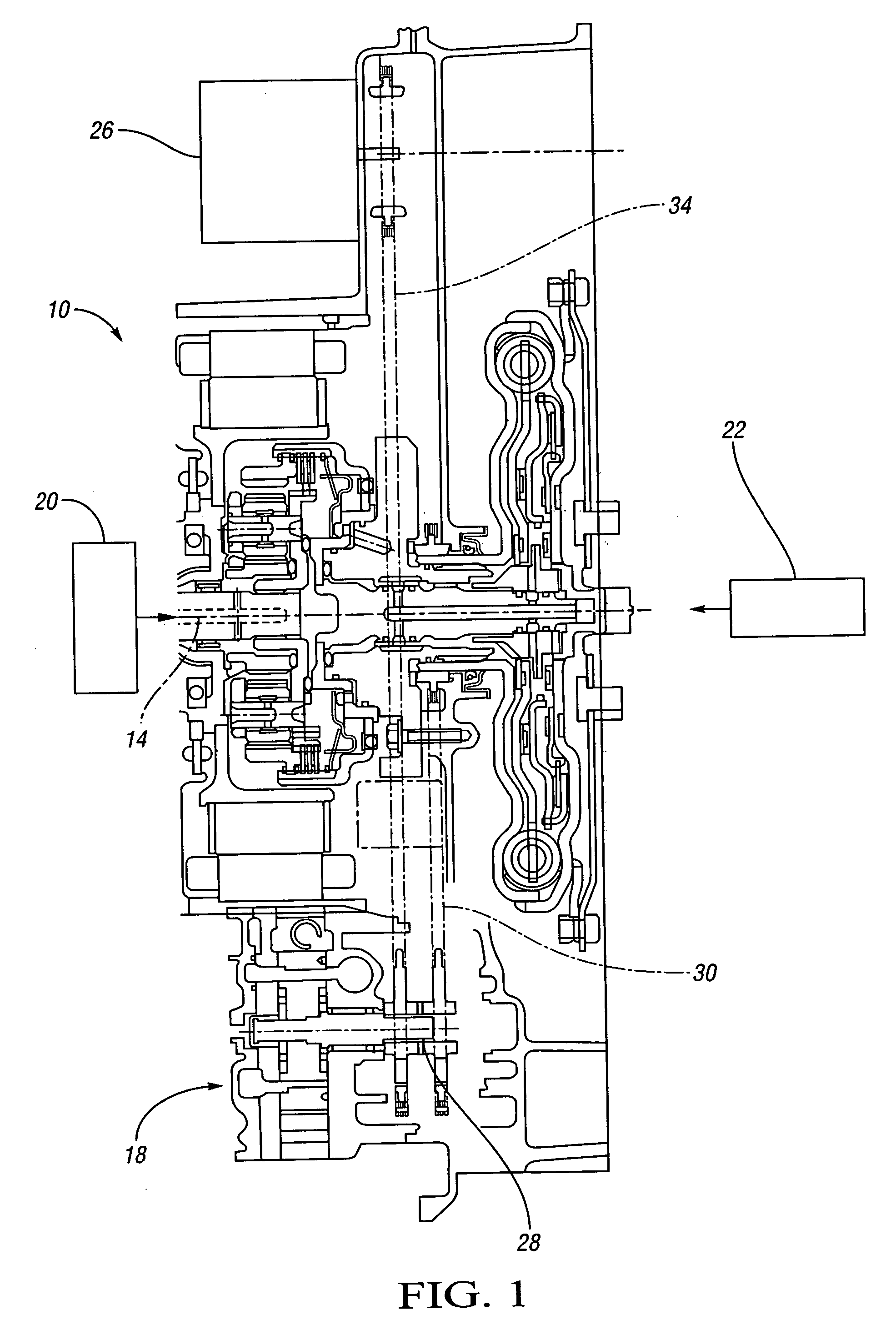
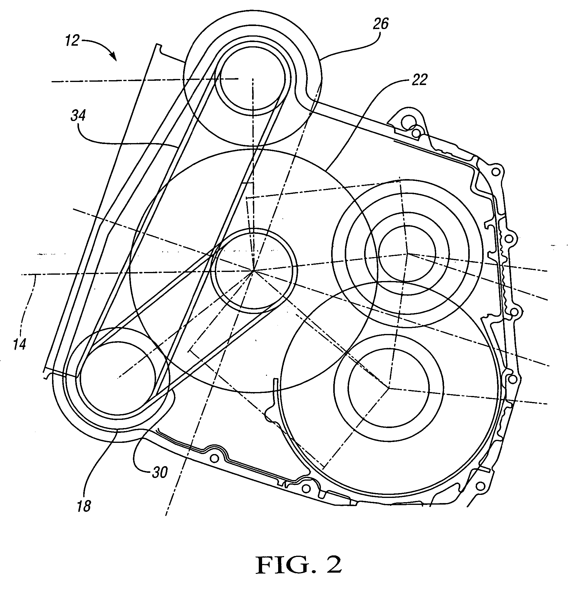
[0012]FIG. 1 illustrates a transmission system 10 of a gasoline / electric vehicle having a center axis 14. FIG. 2 is a representation of the pumping system 12 of the transmission system 10 of FIG. 1. Referring to FIGS. 1 and 2, the pumping system 12 comprises a pump 18 that supplies fluid to power the vehicle clutches as well as providing cooling and lubrication to the transmission systems. The pump 18 is functionally connected to the first mechanical power source or engine 22 and a second electrical power source or electric motor 26 by a first connection apparatus 30 and a second connection apparatus 34, respectively. The functional connections through the first and second connection apparatuses 30, 34 may provide power to the pump 18 either directly from each power source 22, 26 or transferred through devices such as belts or chains, as illustrated in FIG. 2. The connections between the pump 18 and the engine 22 and between the pump 18 and the electric motor 26 include a pair of on...


PUM


Abstract

A pumping system for a transmission system having a single pump functionally connected to a mechanical power source and an electrical power source is provided. The connections between the pump and the mechanical power source and electrical power source include at least one roller clutch, which permits only one of the power sources to drive the pump at any given time. Additionally, the functional connections, which may be chains, provide that the pump and the electrical power source may be located non-coaxial with the center axis of the transmission system, as may be preferred for improved packaging. The dual-chain and roller clutch pumping system is appropriate for gasoline / electric hybrid vehicles where pumping may be necessary when the engine is off and limited packaging space is available in the transmission housing.

Description

CROSS-REFERENCE TO RELATED APPLICATION [0001] This application claims the benefit of U.S. Provisional Application 60 / 604,818 filed Aug. 26, 2004, which is hereby incorporated by reference in its entirety.TECHNICAL FIELD [0002] This invention relates to a pumping system for a hybrid vehicle transmission system having a single pump with dual chains and a roller clutch. BACKGROUND OF THE INVENTION [0003] A vehicle transmission system is equipped with a pump to supply fluid to power vehicle clutches as well as to provide lubrication and cooling to the transmission systems. The vehicle engine provides power to a pump in many previous pumping systems and, thus, the systems are only operable when the engine is running. In these previous systems, there is no mechanical ability to run the hydraulic pump when the engine is not running. However, situations exist where the engine is off but vehicle mechanisms are in motion, such as when a battery powers an electric / gasoline hybrid vehicle. Anot...

Claims


Application Information

Patent Timeline
IPC IPC(8): F16D13/74B60K6/40B60K6/445F16H57/04
CPCB60K6/40B60K6/445B60W10/30F04B9/02F04B17/05Y02T10/6239F04C15/008F04C2240/45F16H57/0439F16H61/0025F04C15/0057Y02T10/62
Inventor PASHNIK, RICHARD A.DIEMER, JOHN A.
Owner GM GLOBAL TECH OPERATIONS LLC
Learn More