
Detection and removal of image occlusion errors

a technology of image occlusion and detection, applied in the field of image processing techniques, can solve the problems of leakage in a particular direction, limitation also speeds up the correspondence process significantly, etc., and achieve the effect of accurately identifying the occluded areas, poor match points, and significant speeding up the correspondence process

Inactive Publication Date: 2005-03-08
CANON KK
View PDF17 Cites 75 Cited by
  • Summary
  • Abstract
  • Description
  • Claims
  • Application Information

AI Technical Summary

Benefits of technology

The patent describes a system and method for detecting and eliminating errors in images caused by image occlusions. The method uses traditional correspondence methods to match points in two images, and a second search is performed based on the results of the first search to generate a more accurate match. The second search is limited by the way in which occlusions manifest themselves as errors during correspondence. The system can also remove any additional errors in the final images and create a separate disparity map for each color coordinate. The technical effect of this patent is to improve the accuracy and efficiency of detecting and eliminating errors in images caused by image occlusions.

Problems solved by technology

More specifically, incorrectly matched points often cause leakage in a particular direction depending on the direction of image used in the first search.
This limitation also speeds up the correspondence process significantly, as only a portion of the points in the row: is used during the correspondence search.

Method used


Image

  • Detection and removal of image occlusion errors
  • Detection and removal of image occlusion errors
  • Detection and removal of image occlusion errors

Examples


second embodiment

One benefit of this second embodiment is that it provides greater confidence in the accuracy of the points in the image. This can be of particular use in those applications where potentially unknown areas can simply be avoided. In machine vision applications such as robotics, for example, a moving robot can simply avoid black areas as potentially corresponding to an object that may prevent movement. This may lead to a more circuitous route, but is a better calculated choice when potentially expensive equipment is involved.

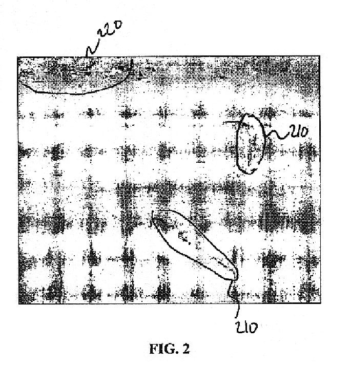
The results of the second embodiment could also be used in combination with the first embodiment to create a disparity confidence map. For example, the brightness of a particular pixel in the disparity map can be adjusted based on the second algorithm. All points in image 4A that correspond to potential erroneous points in image 5A could have a lower brightness value while “correct” points have a higher brightness value. Other applications and embodiments could als...


PUM


Abstract

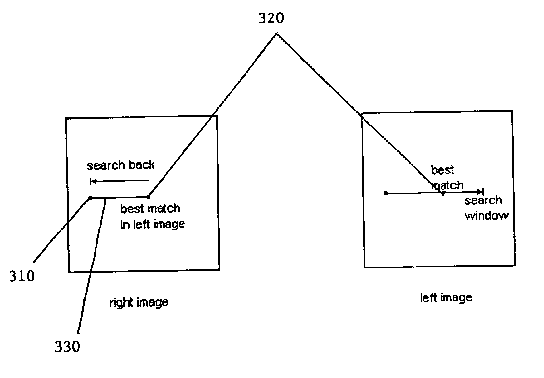
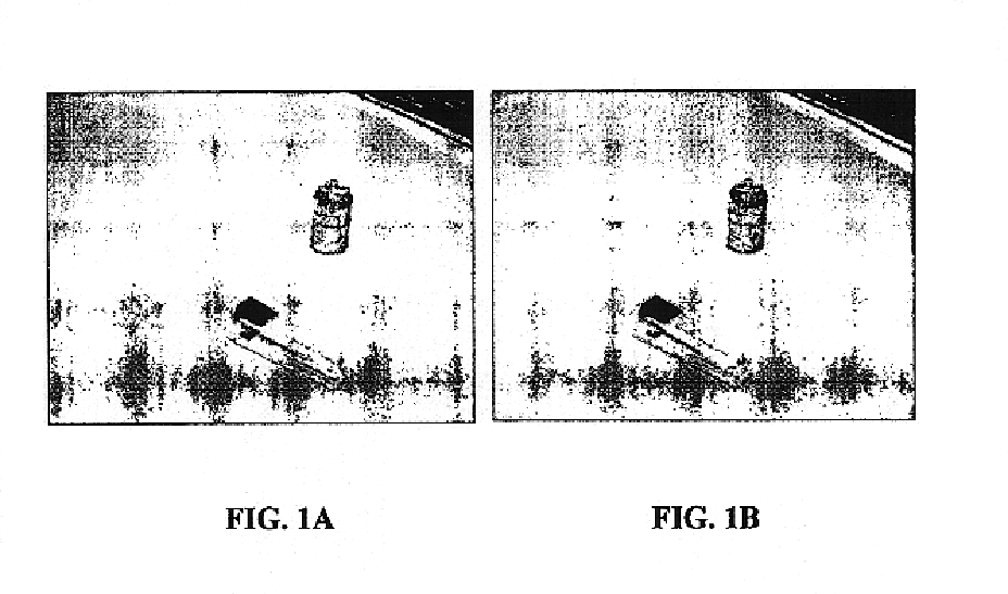
A system, method, and computer-readable medium for detecting and eliminating correspondence errors associated with image occlusions. In a first embodiment of the invention, the method applies traditional correspondence methods for matching points in two images, a left image (FIG. 1A) and a right image (FIG. 1B), taken of the same scene. The method applies the correspondence method to locate a matching a point (310) in the right image (FIG. 1B) with a “best match” point (320) in the left image (FIG. 1A). A set of matching points (310, 320) is generated. A second search is then performed by using the best match point (320) in the right image (FIG. 1B) as the basis for an additional correspondence search in the left image (FIG. 1A). The range of match candidates in the second search is such that points to the left of the starting point (310) are not tested as match candidates. The point (330) generated in the second search may be the same point (310) that was used in the first search or may be a different point altogether. The results of the second search are selected as the match candidates.

Description

BACKGROUND OF THE INVENTION1. Field of the InventionThis invention is related to image processing techniques. More specifically, this invention is a system, method, and computer-readable medium for removing stereo matching errors caused by image occlusions.2. Related ArtA stereo matching algorithm, which can produce a dense and sharp depth map as an active range finder, is a key technology for many stereo applications including object recognition, three-dimensional object modeling, vehicle navigation, and geometric inspection. In order to generate a three-dimensional map or image of a scene, however, different images of the scene must be matched properly. One of the major problems to properly matching points in the images is caused when occluding contours coincide. Occluding contours coincide when a point, which is visible in the right image, is not visible in the left image and therefore does not really have a matching point. Alternatively, occluding errors can also occur at the bo...

Claims


Application Information

Patent Timeline
Patent Type & Authority Patents(United States)
IPC IPC(8): G01C11/06G01C11/00G06T7/00
CPCG06T7/0075G01C11/06G06T7/593
Inventor BERESTOV, ALEXANDER
Owner CANON KK
Learn More