
Catalytically enhanced filtration apparatus

a technology of filtration apparatus and catalytic enhancement, which is applied in the field of filters, can solve the problems of sorbents, aerosol tar, and up plugging filters,

Inactive Publication Date: 2005-03-08
SIEMENS ENERGY INC
View PDF5 Cites 77 Cited by
  • Summary
  • Abstract
  • Description
  • Claims
  • Application Information

AI Technical Summary

Benefits of technology

[0013]A hot gas filtration apparatus constructed in accordance with this invention includes a vessel, a plurality of filter elements mounted within the vessel and positioned such that hot gas flows through said filter elements, with each of said filter elements having a porous body, and a catalytic layer on surfaces of the porous body. The porous body of the filter element may include one of: a porous ceramic monolithic matrix, a continuous fiber reinforced ceramic composite (CFCC) matrix, a metallic matrix, an intermetallic matrix, a superalloy, and a metal-ceramic composite matrix. When the porou

Problems solved by technology

In addition to the production of unwanted gasses, aerosol tars that are formed during coal gasification are not readily removed from gas streams by conventional means, and thus often end up plugging filters or fouling fuel cells, turbines, or sorbents.

Method used


Image

  • Catalytically enhanced filtration apparatus
  • Catalytically enhanced filtration apparatus
  • Catalytically enhanced filtration apparatus

Examples


Embodiment Construction

lter element constructed in accordance with the present invention;

[0019]FIG. 6 is an enlarged schematic representation of a portion of the candle filter element of FIG. 5;

[0020]FIG. 6a is an enlarged detail of a portion of the candle filter element of FIG. 6; and

[0021]FIG. 7 is an enlarged schematic sectional view of a portion of the wall of the candle filter element of FIG. 5.

DESCRIPTION OF THE PREFERRED EMBODIMENTS

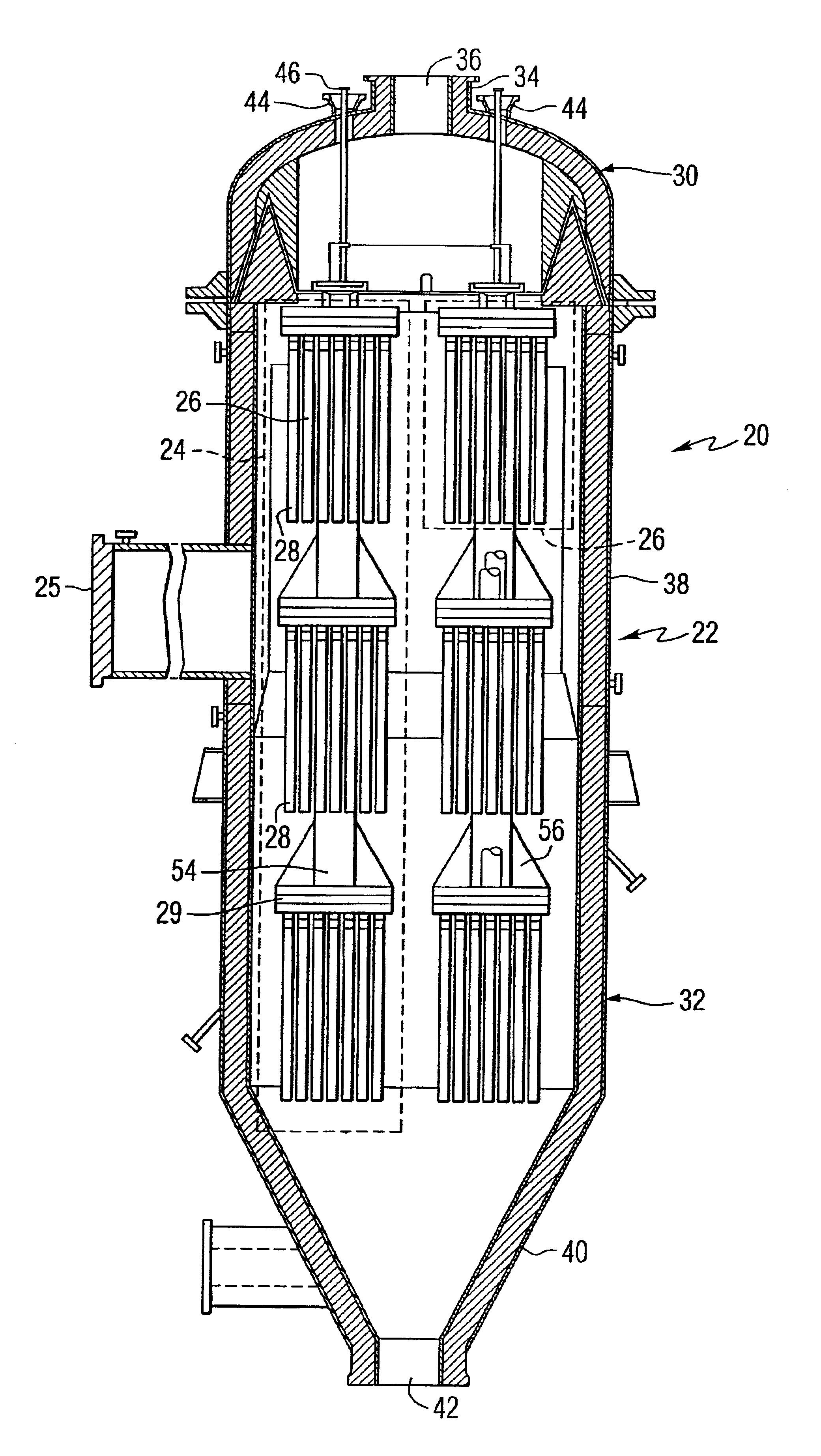
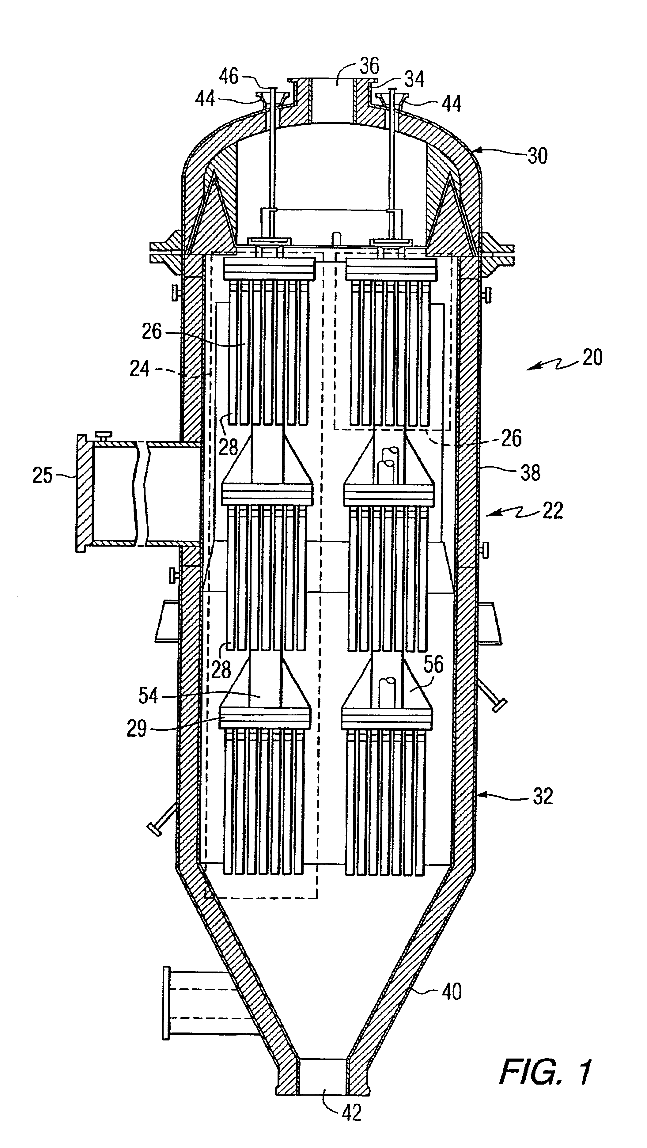
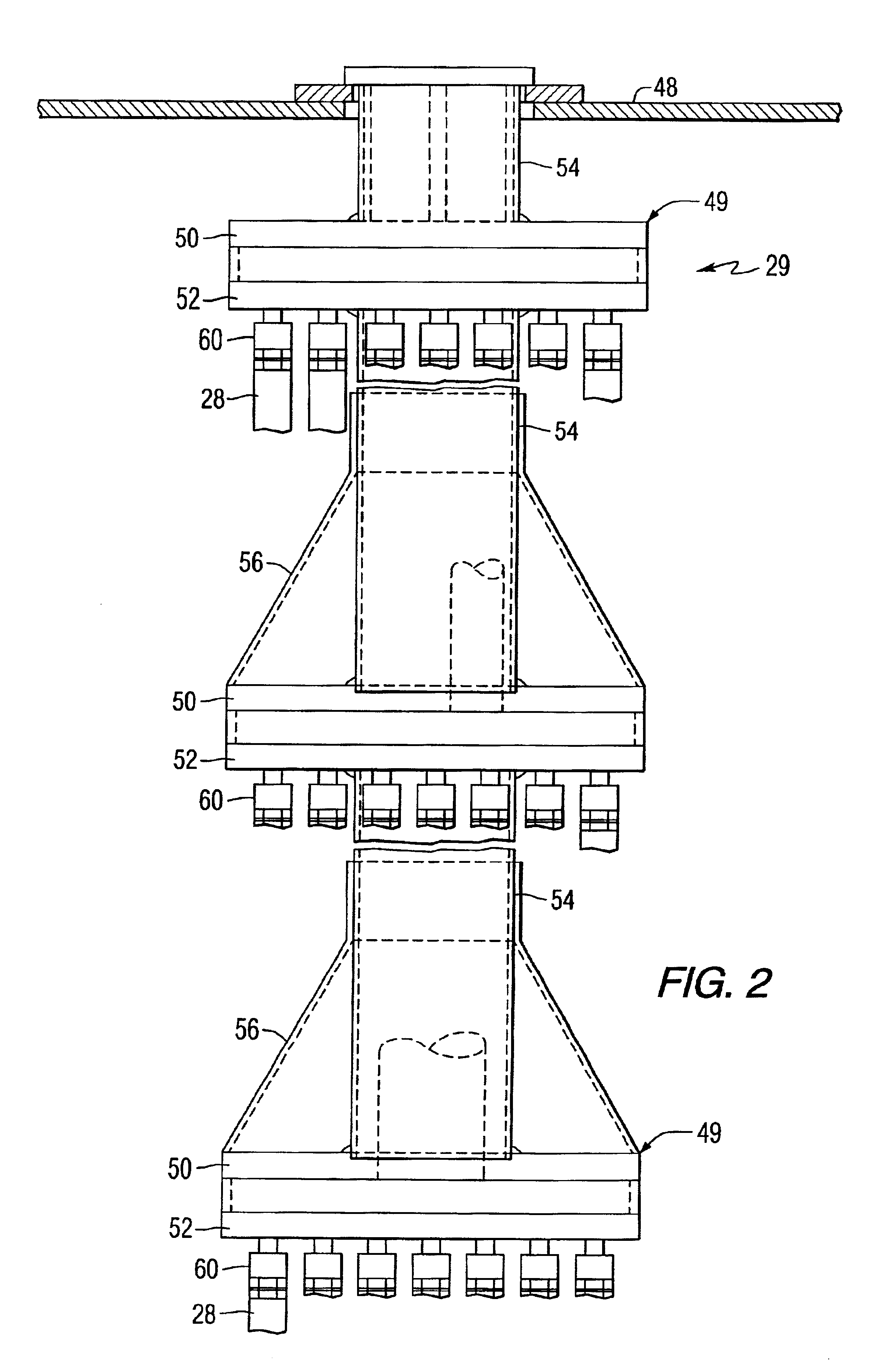
[0022]The preferred embodiment of this invention incorporates catalytically enhanced filter elements into a filter assembly similar to that disclosed in U.S. Pat. No. 5,876,471. Referring to the drawings, FIG. 1 shows a filter apparatus 20 for separating particulate matter from a gas stream that includes filter elements constructed in accordance with this invention. This apparatus includes a pressure vessel 22 in which there are mounted a plurality of clusters 24 comprising a plurality of filter element arrays 26. Each of these filter element arrays 26 includes a plurali...


PUM

PropertyMeasurementUnit
Electrical resistanceaaaaaaaaaa
Metallic bondaaaaaaaaaa

Abstract

A hot gas filtration apparatus includes a vessel, a plurality of filter elements mounted within the vessel and positioned such that hot gas flows through said filter elements, with each of said filter elements having a porous body, and a catalytic layer on surfaces of the porous body. The porous body of the filter element may include one of: a porous ceramic monolithic matrix, a continuous fiber reinforced ceramic composite (CFCC) matrix, a metallic matrix, an intermetallic matrix, a superalloy, and a metal-ceramic composite matrix. When the porous body is a nonoxide ceramic, a metallic matrix, an intermetallic matrix, a superalloy, or a metal-ceramic composite matrix, the invention further includes an oxidative resistant layer coating surfaces within the porous body, and the catalytic layer is on the oxidative resistant layer. A porous particulate removal membrane can be positioned on one or more surfaces of the filter element. The porous membrane can also provide a surface for one or more catalysts. The catalysts on the porous surface of the membrane(s) can be the same as or different from the catalysts on surfaces within the porous body.

Description

BACKGROUND OF THE INVENTION[0002]This invention relates to filters, and more particularly to filter elements that are useful in hot gas filter assemblies.[0003]Many processes exist wherein a hot gaseous medium is produced which contains particulate material that must be separated from a gaseous medium, either to prevent pollution, or to remove hazardous material. High temperature filtration of particulates has become an important component in many emerging technologies. Advanced coal conversion technologies, such as fluid bed gasification and combustion, are dependent upon the successful removal of particulates at temperatures in the range of about 500° C. to 1000° C. Other applications which benefit from high temperature filtration range from gas cleaning for biomass gasification to power generation from the incineration of municipal solid wastes. These applications require the removal of particulates from gas streams at high temperature so that process equipment, such as rotating ...

Claims


Application Information

Patent Timeline
IPC IPC(8): B01D46/24B01D53/86B01D53/88B01D39/20B01D46/00B01J8/00C10J3/84F23G7/07F23J15/02
CPCB01D39/2027B01D46/002B01D46/0095B01D46/2407B01D53/8631B01D53/885B01J8/006C10J3/84F23G7/07F23J15/025B01D39/2068Y02E20/16B01D2273/20B01J2219/30223C10J2200/09Y02E20/18B01D46/58
Inventor ALVIN, MARY ANNE
Owner SIEMENS ENERGY INC
Learn More